Volvo 850. Manual — part 66
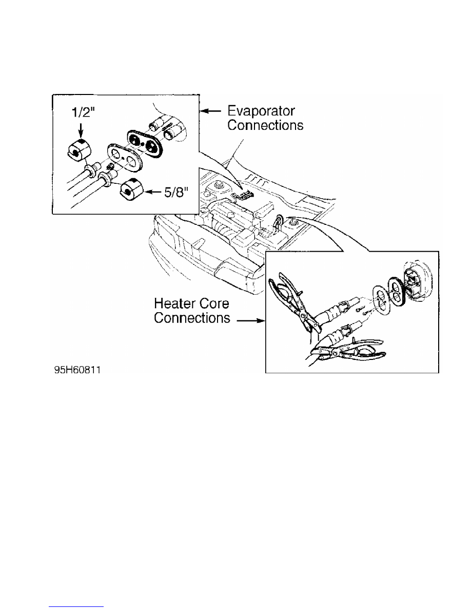
Fig. 17: Identifying Evaporator & Heater Core Connections
Courtesy of Volvo Cars of North America.
COMPRESSOR
Removal & Installation
1) Disconnect negative battery cable. Discharge A/C system,
using approved refrigerant recovery/recycling equipment. Remove air
intake hose and hose connection to fan cover. Remove control box air
intake hoses and Electronic Control Units (ECUs) from control box.
2) Remove control box air intake hoses and disconnect inlet
hose connection from fan cover. Remove fan cover. Disconnect relays
and cables from fan cover (2 tie straps).
3) Remove 4 screws and fan cover. Remove relay shelf and
spacers. Disconnect 2-pin connector from fan relay and connector from
fan motor. Remove fan cover. See Fig. 18.
4) Shield radiator. Disconnect harness connectors from
compressor. Disconnect snap-on connectors on receiver-drier. Remove
right side headlight casing. Remove receiver-drier bracket screw.
5) Remove air guide. With bracket hooked onto side member,
lift receiver/drier out. Plug receiver-drier pipe ends. Disconnect
drive belt.
6) Disconnect compressor connector and temperature sensor.
Remove compressor. To install, reverse removal procedure. Lubricate
NEW "O" rings with compressor oil.
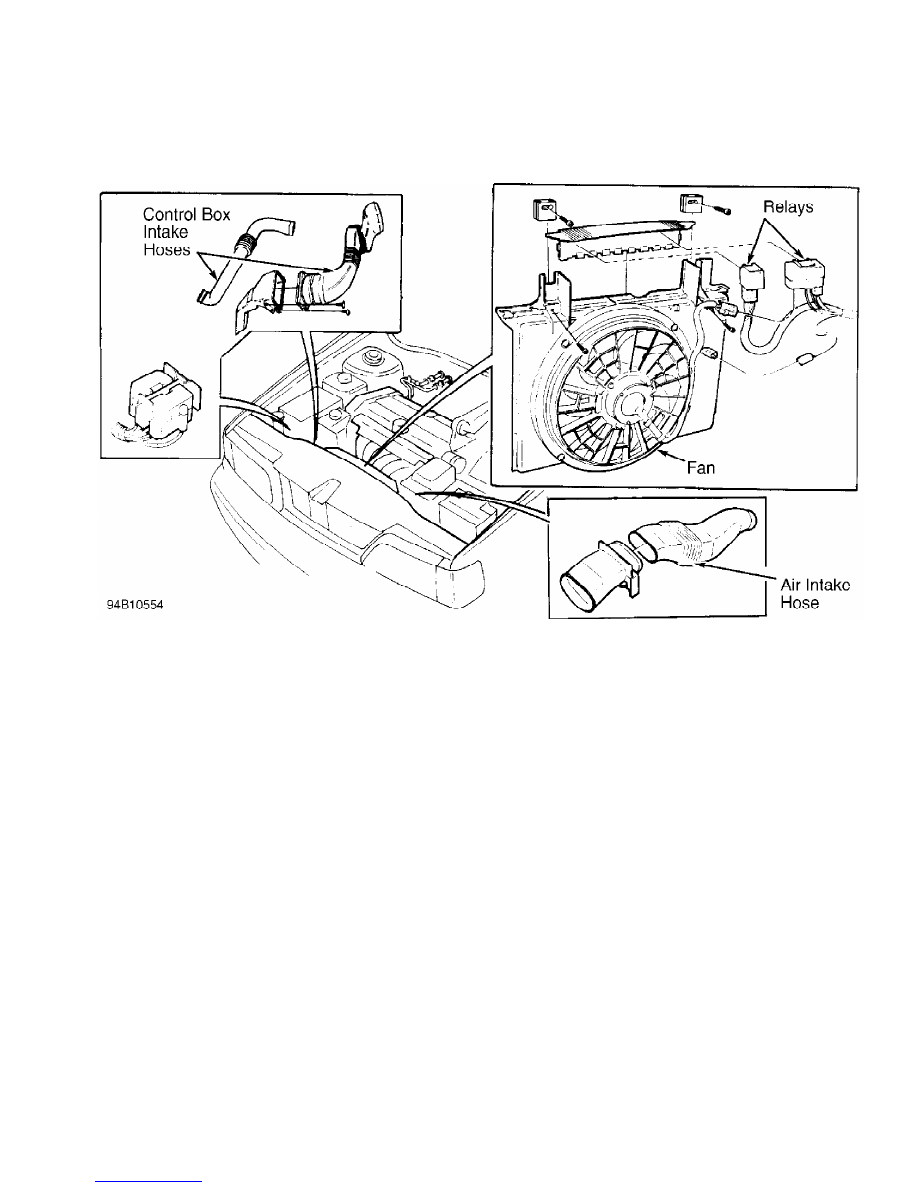
Fig. 18: Removing Cooling Fan Components
Courtesy of Volvo Cars of North America.
CONDENSER
NOTE: When replacing condenser, always replace "O" rings and
snap-on connections.
Removal & Installation
1) Disconnect negative battery cable. Discharge A/C system,
using approved refrigerant recovery/recycling equipment. Disconnect
air intake hose. Remove hose connector to fan cover.
2) Remove Electronic Control Units (ECUs) from control unit
box. Disconnect control unit box air intake hoses. Remove inlet hose
connector to fan cover. Disconnect relays from relay casing. Remove 4
screws to disconnect fan cover, and fold cover back towards engine.
Remove relay shelf and spacers. See Fig. 18.
3) Disconnect pipes from condenser. Disconnect high-pressure
sensor connector. Remove high pressure sensor. Disconnect condenser
screws. Lift condenser out.
4) To install, reverse removal procedure. Transfer high-
pressure sensor and rubber gasket to NEW condenser. Lubricate NEW "O"
rings with compressor oil.
DAMPER MOTOR
Removal & Installation
Turn ignition off. Remove soundproofing from center console.
Remove glove compartment. Disconnect connector from damper motor
(located on A/C control unit). Hold catches in on both sides of damper
motor and pull motor straight out. See Fig. 19. To install, reverse
removal procedure.
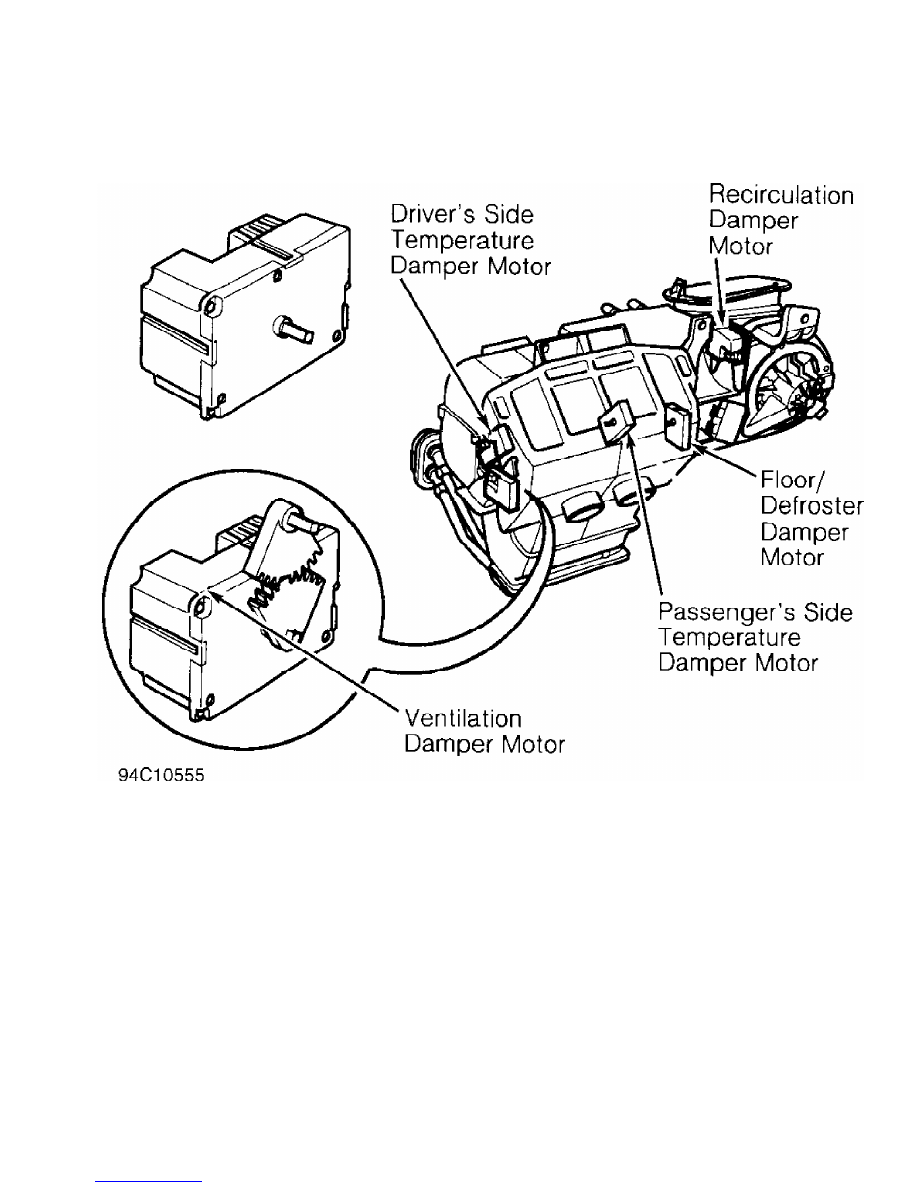
Fig. 19: Removing Damper Motor
Courtesy of Volvo Cars of North America.
DASHBOARD
NOTE: Dashboard consists of 5 main sections: upper frame, lower
frame (left and right), defroster duct and dashboard cover.
Except for dashboard cover, all the main sections are glued
together and cannot be separated.
Removal & Installation
1) Disconnect negative battery cable. Disable air bag system.
See AIR BAG RESTRAINT SYSTEM article in the ACCESSORIES/SAFETY
EQUIPMENT section. From engine compartment, remove windshield wiper
nuts, windshield wiper well cover panel screws and wiper well. Remove
wiper motor mountings.
2) From passenger compartment, remove air bag module. Mark
steering wheel position relative to steering wheel shaft. Remove
steering wheel nuts and steering wheel. Remove steering wheel stalks.
3) Remove steering wheel stalk connector. Remove left and
right side sound proofing, side defroster, left and right side speaker
covers, and speakers.
4) Remove dashboard mounting screws and glove box. Remove
radio. Reach underneath ECC control module, and push up on locking
button to release ECC control module. Remove ECC control module from
dashboard. Remove cigarette lighter connector. Lift off dashboard. To
install, reverse removal procedure.
DASHBOARD COVER
NOTE: When adjusting air-mix damper, only the dashboard cover
needs to be removed.
Removal & Installation
1) Remove side defroster cover plate screws. Remove dash
panel vents by rolling vents down and pulling out. Both vents and air
duct on right side must be removed.
2) Remove left and right side speakers. Remove dashboard
cover screws and lift off dashboard cover. To install, reverse removal
procedure. Ensure hook on right side of dashboard cover plate engages
into upper frame section.
DUCT TEMPERATURE SENSOR
Removal & Installation
1) Turn ignition off. Remove radio. Reach under ECC control
module, push up on locking button, and release ECC control module.
Remove ECC control module from dashboard.
2) Remove left and right side sound insulation from center
console. Remove glove box. Remove duct temperature sensor connector
and pull down on duct temperature sensor. To install, reverse removal
procedure.
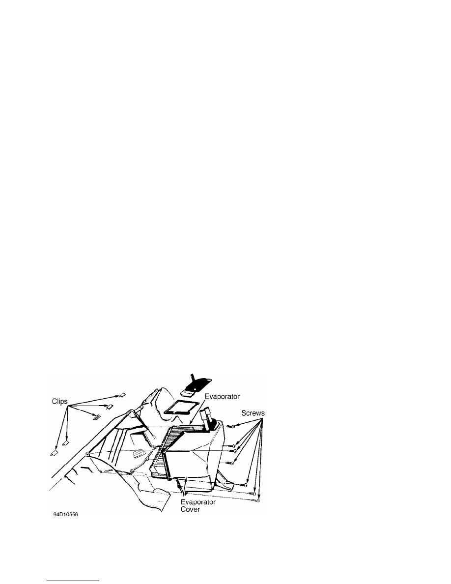
EVAPORATOR
Removal & Installation
Disconnect negative battery cable. Remove dashboard assembly.
See DASHBOARD. Remove climate control unit. See CLIMATE CONTROL UNIT.
Remove evaporator cover screws and clips. Lift out evaporator. See
Fig. 20. To install, reverse removal procedure.
Fig. 20: Removing Evaporator
Courtesy of Volvo Cars of North America.
HEATER CORE
Нет комментариевНе стесняйтесь поделиться с нами вашим ценным мнением.
Текст