Volvo S90 Recharge Plug-in Hybrid (2021 year). Manual in english — page 24
||
DRIVER SUPPORT
410
Market
ACC
& PA
BLIS
Symbol
Type approval
Mexico
✓
IFETEL: RLVDEL215-0299
✓
Radar de corto alcance
RS4
Hella KGaA Hueck & Co
IFETEL: RLVHERS17-0286
La operación de este equipo esta sujeta a las siguientes dos condiciones: (1) es posible que
este equipo o dispositivo no cause interferencia perjudicial y (2) este equipo o dispositivo debe
aceptar cualquier interferencia, incluyendo la que pueda causar su operación no deseada.
Moldova
✓
✓
Nigeria
✓
Connection and use of this communications equipment is permitted by the Nigerian
Communications Commission.
Oman
✓
-------------------------------------------------------------------------------------------------------------------------------------------------------------
DRIVER SUPPORT
}}
411
Market
ACC
& PA
BLIS
Symbol
Type approval
Russia
✓
Serbia
✓
И
011 14
✓
И
011 17
Singapore
✓
DA 105753
✓
DA 103238
South Africa
✓
TA-2014/1824
✓
TA-2016/3407
-------------------------------------------------------------------------------------------------------------------------------------------------------------
||
DRIVER SUPPORT
412
Market
ACC
& PA
BLIS
Symbol
Type approval
South Korea
✓
Certification No.
MSIP-CMI- DPH-L2C0054TR
✓
R-CMM-HLA-RS4
이
기기는
무용
(A
급
)
전자파
적합기기로서
판
매자
또는
사용
자는
이
점을
주의하시기
바
라
며
,
가정외의
지역에서
사용
하는
것을
적으
로
합니다
Taiwan
✓
CCAB15LP0560T3
✓
CCAB17LP0470T5
警語
經型式認證合格之低 率射頻電機
,
非經許可
,
公司 商號或使用者均不得擅自變更頻率
大 率或變更原設計之特性及 能
低 率射頻電機之使用不得影響飛航安全及干擾合法通
信
;
經發現有干擾現象時
,
應立即停用
,
並改善至無干擾時方得繼續使用
前項合法通信
,
指依電信
法規定作業之無線電通信 低 率射頻電機須忍受合法通信或工業
科學及醫療用電波輻射性
電機設備之干擾
Thailand
✓
ค อ ท ค
ค ล อ
ค
อ คลอ
ฐ
อ อ
อ
ทช
.
ค อ
ท ค
ค
คล
ล
อ คลอ
ฐ ค
ลอ
อ
อ
ช ค อ
ท ค
ค ท ค
ท ค
ค
ช
ํ
-------------------------------------------------------------------------------------------------------------------------------------------------------------
DRIVER SUPPORT
}}
413
Market
ACC
& PA
BLIS
Symbol
Type approval
Ukraine
✓
Delphi
є
,
щ
RACAM/SRR2
є
(
ь
)
(
КМ №
679
24
2009 .)
ь
Delphi
: Delphi.
: 24,05 – 24,25
ь
: 20
Б
(
.) EIRP
✓
HELLA GmbH & Co. KGaA
є
,
щ
RS4
є
2014/53/
Є
.
ь
:
www.hella.com/vcc
: 24,05 – 24,25
ь
: 20
Б
(
.) EIRP
Vietnam
✓
Zambia
✓
-------------------------------------------------------------------------------------------------------------------------------------------------------------
||
DRIVER SUPPORT
* Option/accessory.
414
Type approval for radio equipment
Market
Symbol
Type approval
Europe
Hereby, Volvo cars, declares that all radio equipment's are in compliance with the essential requirements and other
relevant provisions of Directive 2014/53/EU.
Japan
R 204-750001
This device is granted pursuant to the Japanese Radio Law and the Japanese Telecommunications Business Law. This
device should not be modified (otherwise the granted designation number will become invalid).
For detailed information on type approval, go
to volvocars.com/support.
Related information
•
•
•
•
-------------------------------------------------------------------------------------------------------------------------------------------------------------
DRIVER SUPPORT
}}
* Option/accessory.
415
Camera unit
The camera unit is used by several driver sup-
port systems and has the task of for example
detecting lane lines or traffic signs.
Location of the camera unit
The camera unit is used by the following func-
tions:
•
Adaptive cruise control
*
•
Pilot Assist
*
•
Lane assistance
*
•
Steering assistance at risk of collision
•
City Safety
•
Driver Alert Control
*
•
Road Sign Information
*
•
Active main beam
*
•
Park Assist
*
Related information
•
Driving support systems (p. 286)
•
Limitations for camera and radar unit
(p. 415)
•
Recommended maintenance for camera
and radar unit (p. 418)
Limitations for camera and radar
unit
The camera and radar unit has certain limita-
tions – which in turn also limit those func-
tions that use the unit. A driver should be
aware about the following examples of limita-
tions.
-------------------------------------------------------------------------------------------------------------------------------------------------------------
||
DRIVER SUPPORT
416
Common limitations for camera and
radar
Blocked unit
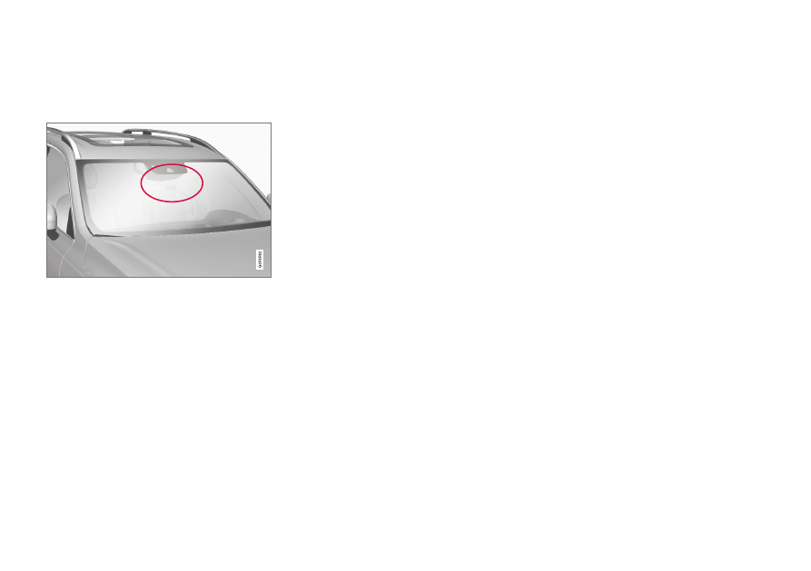
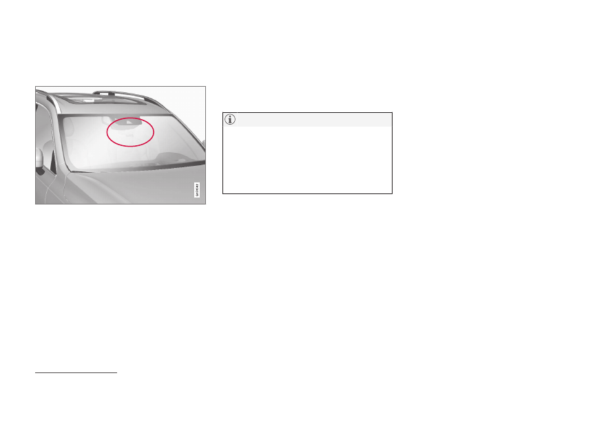
The marked area must be cleaned regularly and kept
free from stickers, objects, shade film, etc.
The camera unit is placed inside the upper
section of the windscreen together with the
car's radar unit.
Do not place, stick or mount anything on the
inside or outside of the windscreen, in front of
or around the camera and radar unit – this
may interfere with camera and radar-based
functions. This may result functions being
reduced, being switched off completely or giv-
ing incorrect function responses.
High temperature
At very high temperatures the camera and
radar unit can temporarily be switched off for
about 15 minutes after the engine is started so
as to protect the unit's electronics. The cam-
era and radar unit restarts automatically when
the temperature has fallen sufficiently.
Damaged windscreen
If not rectified it can lead to reduced per-
formance for the driver support systems
that use the camera and radar unit. This
may result functions being reduced, being
switched off completely or giving incorrect
function responses.
The following is also applicable so as not to
risk incorrect function for the driver supports
that use the radar unit:
•
If a scratch, crack or stone chip appears
on the windscreen in front of any of the
"windows" for the camera and radar unit
and covers an area of
approx. 0.5 × 3.0 mm (0.02 × 0.12 in.) or
more, a workshop
139
must be contacted
so that the windscreen can be replaced.
•
Volvo recommends
not
repairing cracks,
scratches or stone chips in the area in
front of the camera and radar unit – the
entire windscreen should be replaced
instead.
•
Before replacing a windscreen, contact a
workshop
139
to verify that the correct
windscreen has been ordered and will be
fitted.
•
The same type of windscreen wipers or
windscreen wipers approved by Volvo
must be fitted when the windscreen is
replaced.
•
When replacing the windscreen, the cam-
era and radar unit must be recalibrated by
a workshop
139
to ensure the functionality
of all the camera and radar-based systems
in the car.
Further limitations for radar
Vehicle speed
The radar unit's ability to detect a vehicle
ahead is greatly reduced if the speed of the
vehicle ahead is very different to the speed of
your own car.
139
An authorised Volvo workshop is recommended.
-------------------------------------------------------------------------------------------------------------------------------------------------------------
DRIVER SUPPORT
}}
* Option/accessory.
417
Limited field of vision
The radar unit has a limited field of vision. In
some situations another vehicle is not
detected, or the detection is made later than
expected.
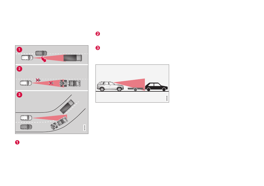
The radar unit's field of vision
Sometimes the radar unit is late at detect-
ing vehicles at close distances - e.g. a
vehicle that drives in between your car and
the vehicle ahead.
Small vehicles, such as motorcycles, or
vehicles not driving in the centre of the
lane can remain undetected.
In bends, the radar unit may detect a dif-
ferent vehicle than intended or lose a
detected vehicle from view.
Low trailers
Low trailer in radar shadow
Low trailers can also be difficult for the radar
unit to detect, or are not detected at all - the
driver should therefore be particularly careful
when driving behind low trailers when the
adaptive cruise control
*
or Pilot Assist
*
is acti-
vated.
Further limitations for camera
Impaired vision
The cameras have limitations similar to the
human eye, i.e. may "see" worse in for exam-
ple intense snowfall or rain, dense fog, heavy
dust storms and snow flurries. Under such
conditions, the functions of camera-depend-
ent systems could be significantly reduced or
temporarily disengaged.
Strong oncoming light, reflections in the car-
riageway, snow or ice on the road surface,
dirty road surfaces or unclear lane markings
can also significantly reduce camera function
when it is used to scan the carriageway to
detect pedestrians, cyclists, large animals and
other vehicles.
-------------------------------------------------------------------------------------------------------------------------------------------------------------
||
DRIVER SUPPORT
* Option/accessory.
418
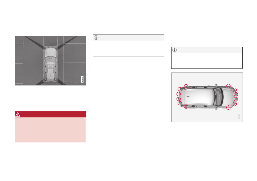
Further limitations for Park assist
camera
*
Blind sectors
There are "blind" sectors between the cameras' fields
of vision.
In the park assist camera's 360° view
*
obsta-
cles/objects may "vanish" in the gaps
between the individual cameras.
WARNING
Pay attention to the possibility that, even if
it only looks like a relatively small part of
the image is obscured, a relatively large
sector could be hidden from view. An
obstacle could thereby go undetected until
the car is very close to it.
Light conditions
The camera image is adjusted automatically
according to prevailing light conditions.
Because of this, the image may vary slightly in
brightness and quality. Poor light conditions
can result in reduced image quality.
A bike carrier or other accessory mounted
on the rear of the car could obscure the
camera's view.
Related information
•
•
•
Recommended maintenance for camera
and radar unit (p. 418)
•
•
Volvo Cars support site (p. 23)
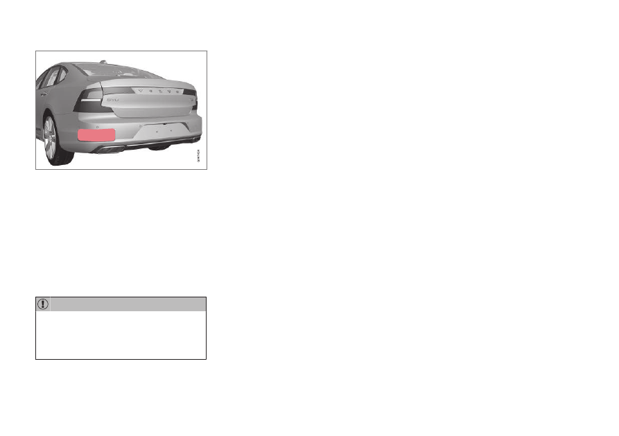
Recommended maintenance for
camera and radar unit
In order that the camera and radar units shall
function correctly, they must be kept clear of
dirt, ice and snow, and be cleaned regularly
with water and car shampoo.
Dirt, ice and snow covering the sensors
may cause incorrect warning signals,
reduced or no function.
Location of the parking sensors
-------------------------------------------------------------------------------------------------------------------------------------------------------------
DRIVER SUPPORT
* Option/accessory.
419
Location of rear radar units. Keep the surface indi-
cated clean – on both the left and right-hand sides of
the car.
•
To ensure best possible functionality, the
surfaces in front of the sensors must be
kept clean.
•
Do not affix any objects, tape or labels in
the area of the sensors.
•
Clean camera lenses regularly with luke-
warm water and car shampoo - be careful
not to scratch the lenses.
Maintenance of driver support components
must only be performed at a workshop –
an authorised Volvo workshop is recom-
mended.
Related information
•
•
•
Limitations for camera and radar unit
(p. 415)
•
-------------------------------------------------------------------------------------------------------------------------------------------------------------

DRIVER SUPPORT
420
Symbols and messages for camera
and radar unit
Here are examples of some of the display
messages and symbols regarding the camera
and radar units that can be shown in the
driver display.
Detector blocked
If the driver display shows this sym-
bol and the message
Windscreen
sensor
Sensor blocked, see
Owner's manual
, this means that
the camera and radar unit cannot detect other
vehicles, cyclists, pedestrians and large ani-
mals in front of the car, and that the car's
camera-based and radar-based functions may
be disrupted.
The following table presents examples of pos-
sible causes for a message being shown,
along with the appropriate action:
Cause
Action
The windscreen surface in front of the camera and radar unit is
dirty or covered with ice or snow.
Clean dirt, ice and snow from the windscreen surface in front of the camera
and radar unit.
Thick fog and heavy rain or snow block the radar signals or the
camera view.
No action. Sometimes the unit does not work during heavy rain or snowfall.
Water or snow from the road surface swirls up and blocks the
radar signals or camera view.
No action. Sometimes the unit does not work on a very wet or snow-covered
road surface.
Dirt has appeared between the inside of the windscreen and the
camera and radar unit.
Visit a workshop to have the windscreen inside the unit's cover cleaned - an
authorised Volvo workshop is recommended.
Strong oncoming light
No action. The camera unit is reset automatically in more favourable light con-
ditions.
-------------------------------------------------------------------------------------------------------------------------------------------------------------
DRIVER SUPPORT
421
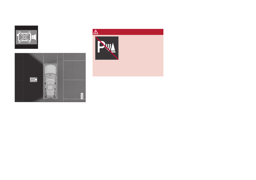
Defective camera
If a camera sector is black
and contains this symbol
then it means that the cam-
era is out of order.
The car's left-hand camera is out of order.
A black camera sector is also shown in the fol-
lowing instances, but then
without
the sym-
bol for defective camera:
•
open door
•
open boot lid
•
folded-in door mirror.
Rear parking camera
WARNING
Pay additional attention
while reversing when this
symbol is shown if a
trailer, bicycle rack or sim-
ilar is mounted and electri-
cally connected to the car.
The symbol indicates that
the parking assistance sensors rearward
are
switched off
and will not warn of any
obstacles.
Related information
•
•
•
Limitations for camera and radar unit
(p. 415)
•
-------------------------------------------------------------------------------------------------------------------------------------------------------------
ELECTRIC OPERATION AND CHARGING
424
General information on electric
drive
Recharge runs like a regular car, but certain
functions differ from a car that only runs on
petrol or diesel. The electric motor drives the
car mostly at low speeds, the petrol engine at
higher speeds, as well as during more active
driving.
The driver display shows some information
that is unique to the Recharge - charging
information, selected drive mode, distance to
empty battery as well as the hybrid battery's
charge level.
It is possible to set the car in different drive
modes while driving, e.g. electric operation
only or, when power is required, both electric
motor and petrol engine. The car calculates a
combination of drivability, driving experience,
environmental impact and fuel economy
according to the drive mode selected.
In order that the car should have optimal func-
tion it is important that the hybrid battery with
associated electrical drive systems, as well as
the petrol engine and its drive systems, have
the correct operating temperature. Battery
capacity may be reduced considerably if the
battery is too cold or too hot. Preconditioning
prepares the car's drive systems and the pas-
senger compartment before departure so that
both wear and energy needs during the jour-
ney are reduced. The range for the hybrid bat-
tery increases.
The hybrid battery which drives the electric
motor is charged via a charging cable but can
also be charged by gentle braking and engine
braking in gear position
B
. The hybrid battery
can also be charged by the car's engine.
Important to know
Car without power
Bear in mind that important functions such as
the servo brakes and power steering are lim-
ited when the car is without power.
WARNING
The brake servo only works when the elec-
tric motor or internal combustion engine is
running.
Towing not permitted
Towing the car is not permitted since this
damages the electric motor.
Exterior engine noise
WARNING
Remember that the car does not emit any
engine noise when it is only powered by
the electric motor and may therefore be
difficult to notice by children, pedestrians,
cyclists and animals. This is especially true
at low speeds, such as in car parks.
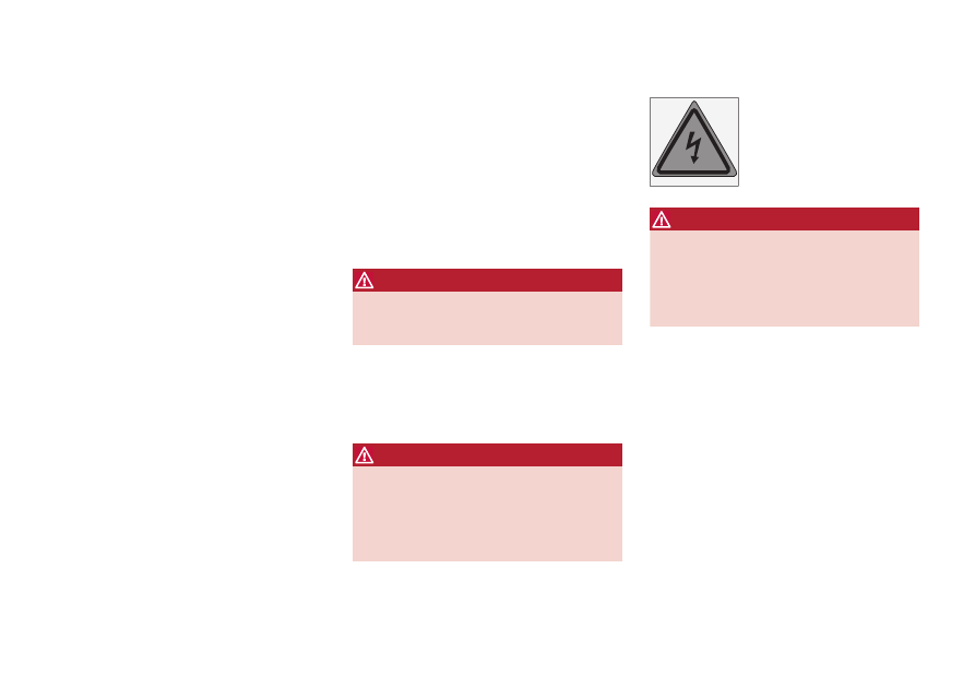
High-voltage current
WARNING
Several components in the car work with
high-voltage current that could be danger-
ous in the event of incorrect intervention.
These components, and all orange-col-
oured cables, must only be handled by
qualified personnel.
Do not touch anything that is not clearly
described in the owner's manual.
Related information
•
Charging the hybrid battery (p. 425)
•
•
•
Start and switch off preconditioning
(p. 223)
•
•
•
-------------------------------------------------------------------------------------------------------------------------------------------------------------
ELECTRIC OPERATION AND CHARGING
}}
425
Charging the hybrid battery
In addition to the fuel tank, as in a conven-
tional car, the car is equipped with a
rechargeable battery - a so-called hybrid bat-
tery of the lithium-ion type.
The hybrid battery is charged using a charging
cable which is located in a storage compart-
ment in the cargo area.
Volvo recommends a charging cable in
accordance with IEC 62196 and IEC
61851 which supports temperature moni-
toring.
The time it takes for the hybrid battery to be
charged is dependent on the charging current
that is used.
The capacity of the hybrid battery decrea-
ses slightly with age and use, which may
result in increased use of the petrol engine
and thereby slightly increased fuel con-
sumption.
WARNING
Replacing the hybrid battery must only be
performed by a workshop - an authorised
Volvo workshop is recommended.
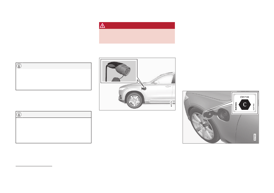
Charging cable handle and charging
input socket
Charging cable handle and charging input socket.
Charging status is indicated in three ways:
•
Indicators on the charging cable's control
unit.
•
Indicator lamp in the car's charging input
socket.
•
Illustration and text in the driver display.
The starter battery is charged when the hybrid
battery is charging and terminated when the
hybrid battery is fully charged.
If the hybrid battery's temperature is below
-10
º
C (14
º
F) or above 40
º
C (104
º
F) then it
may mean that some of the car's functions are
changed or unavailable because the capacity
of the hybrid batteries is reduced outside this
temperature range.
Electric operation is not possible if the tem-
perature of the battery is too low or too high. If
drive mode PURE is then selected, the com-
bustion engine starts.
Decal on the inside of the charging flap
Use charging that is approved for use in the
car in accordance with the identifier
1
on the
inside of the charging input socket flap.
1
Identifiers that comply with CEN standard EN 17186 can be found on the inside of the charging input socket flap.
-------------------------------------------------------------------------------------------------------------------------------------------------------------
||
ELECTRIC OPERATION AND CHARGING
* Option/accessory.
426
Charging with fixed control unit in
accordance with mode 3
2
In certain markets the control unit is installed
within a charging station connected to the
mains power circuit. In which case, the charg-
ing cable has no control unit of its own. There-
fore, use the charging station's charging cable
and follow the instructions at the charging sta-
tion.
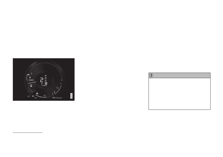
Energy recovery during braking
Indication in driver display during energy recovery.
Energy is regenerated to the battery during
light pressure on the brake pedal or during
engine braking.
The function is available in all drive modes
together with gear position
D
or
B
.
Related information
•
•
•
Opening and closing the hatch for the
charging input socket (p. 431)
•
Starting hybrid battery charging (p. 431)
•
Stopping hybrid battery charging (p. 439)
•
Charging status in the charging cable's
control unit (p. 435)
•
Charging status in the car's charging input
socket (p. 434)
•
Charging status in the car's driver display
(p. 437)
•
Symbols and messages relating to hybrid
drive in the driver display (p. 441)
•
•
•
Long-term storage of vehicles with hybrid
batteries (p. 443)
•
Charging current
Charging current is used for charging the
hybrid battery as well as preconditioning of
the car. Charging takes place with a charging
cable connected to the car's charging input
socket and a 230 V socket
3
(alternating cur-
rent).
When the charging cable is activated, the
driver display shows a message and a lamp in
the car's charging input socket illuminates.
The charging current is mainly used for battery
charging, but is also used for preconditioning
the car. When the car's hybrid battery is
charged, the starter battery is also charged.
Never unplug the charging cable from the
230 V socket (alternating current) while
charging is in progress - there is then a risk
of damaging the 230 V socket. Always
stop charging first before unplugging the
charging cable from the car's charging
input socket and then from the 230 V
socket.
2
European standard - EN 61851-1.
3
The voltage in the socket may vary depending on market.
-------------------------------------------------------------------------------------------------------------------------------------------------------------
ELECTRIC OPERATION AND CHARGING
}}
427
Ensure that the wall socket fuse can han-
dle the specified amperage for the charg-
ing cable.
•
If the weather is very hot or very cold,
some of the charging current is used to
heat/cool the hybrid battery and the
passenger compartment, which results
in a longer charging time.
•
The charging time is extended if pre-
conditioning has been selected. The
time required depends mainly on the
outside temperature.
Charging time
Charging times may vary. The following charg-
ing times are applicable when air conditioning
or any other consumer is not affecting charg-
ing. If charging time seems long, it should be
investigated.
Charging times for charging with 230V
Current intensity
(A)
A
Charging time
(hours)
6
8
10
4
16
3
A
Maximum charging current may vary depending on market.
Fuse
Normally several 230 V consumers are
included in a fuse circuit, so additional con-
sumers (e.g. lighting, vacuum cleaner, electric
drill, etc.) can be on the same fuse.
Related information
•
•
Charging status in the charging cable's
control unit (p. 435)
•
Charging status in the car's driver display
(p. 437)
•
Charging status in the car's charging input
socket (p. 434)
•
Start and switch off preconditioning
(p. 223)
•
Stopping hybrid battery charging (p. 439)
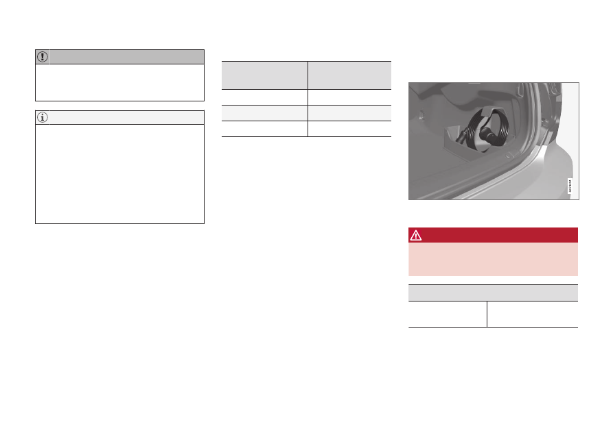
Charging cable
The charging cable with its control unit is
used to charge the car's hybrid battery.
The charging cable is located in the storage compart-
ment to the right of the cargo area.
WARNING
Only use the charging cable provided with
your car or a replacement cable recom-
mended by Volvo.
Specifications, charging cable
Ambient tempera-
ture
-32
º
C to 50
º
C
(-25
º
F to 122
º
F)
-------------------------------------------------------------------------------------------------------------------------------------------------------------
Нет комментариевНе стесняйтесь поделиться с нами вашим ценным мнением.
Текст