Toyota Sequoia (2005). Manual — part 853
RS11Z–01
H23940
Claw
RS–118
–
SUPPLEMENTAL RESTRAINT SYSTEM
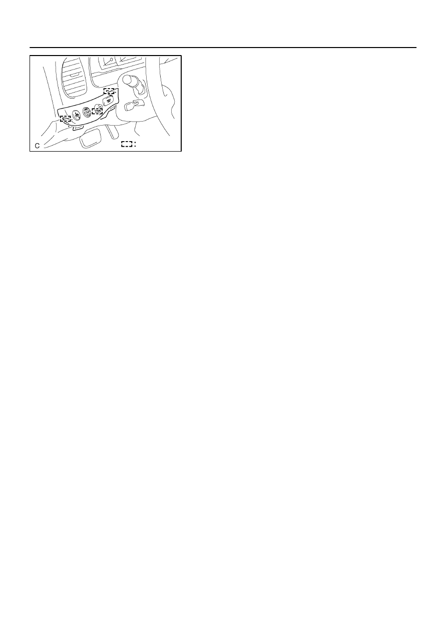
RSCA OFF SWITCH
3401
INSTALLATION
1.
INSTALL SWITCH BASE
(a)
Connect the connectors.
(b)
Engage the 3 claws to install the switch base.
2.
INSTALL LOWER FINISH PANEL (SEE PAGE
3.
CONNECT CABLE TO NEGATIVE BATTERY TERMI-
NAL
4.
PERFORM INITIALIZATION (SEE PAGE
Some system need initialization when disconnecting the cable
from the negative battery terminal.
5.
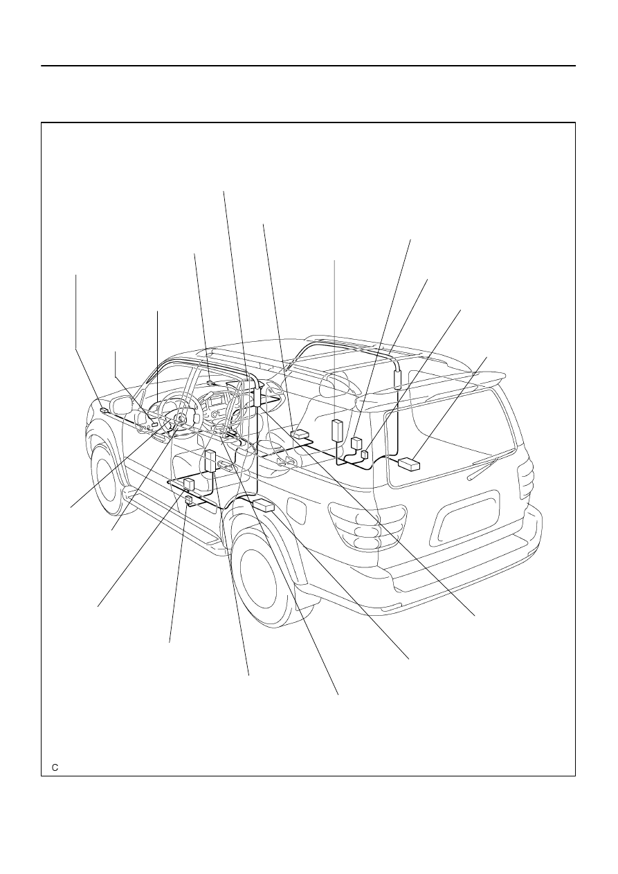
RS0BU–10
H23906
Front Airbag Sensor (LH)
Front Airbag
Sensor (RH)
Front Passenger
Airbag Assembly (RH)
Seat Belt
Pretensioner (RH)
Airbag Sensor Assembly
Seat Belt Pretensioner (LH)
Spiral Cable
Curtain Shield
Airbag Assembly (RH)
Side Airbag
Assembly (RH) (*1)
Side Airbag Sensor
Assembly (RH) (*1)
Side Airbag Assembly (LH) (*1)
Side Airbag Sensor
Assembly (LH) (*1)
Curtain Shield Airbag
Assembly (LH) (*1)
Combination Meter
(Warning Light)
Steering Wheel Pad
(With Airbag)
Curtain Shield Airbag
Sensor Assembly (LH) (*1)
Curtain Shield Airbag
Sensor Assembly
(RH) (*1)
RSCA OFF
Switch (*1)
Occupant Classification
ECU (*1)
(*1) w/ Side Airbag and Curtain Shield Airbag
–
SUPPLEMENTAL RESTRAINT SYSTEM
WIRE HARNESS AND CONNECTOR
RS–119
3402
WIRE HARNESS AND CONNECTOR
LOCATION
RS0BV–08
RS–120
–
SUPPLEMENTAL RESTRAINT SYSTEM
WIRE HARNESS AND CONNECTOR
3403
INSPECTION
HINT:
The SRS wire harness is integrated with the cowl wire harness assembly. The wires for the SRS wire harness
are encased in a yellow corrugated tube and all the connectors in the system except the seat position airbag
sensor connector and occupant classification ECU connectors, colored are yellow.
1.
VEHICLE NOT INVOLVED IN COLLISION
Perform a diagnostic system check (see page
2.
VEHICLE INVOLVED IN COLLISION
(a)
Perform a diagnostic system check (see page
).
(b)
Check breaks in all wires of the SRS wire harness, and exposed conductors.
(c)
Check if the SRS wire harness connectors are cracked or chipped.
RS0BW–07
–
SUPPLEMENTAL RESTRAINT SYSTEM
WIRE HARNESS AND CONNECTOR
RS–121
3404
REPLACEMENT
REPLACEMENT REQUIREMENTS
In the following cases, replace the wire harness or connector with a new one.
Any part of the SRS wire harness or any connector has been found to be faulty in troubleshoot-
ing.
Any part of the SRS wire harness or any connector has been found to be faulty while checking
items (see page
).
CAUTION:
If the wire harness used in the SRS is damaged, replace the whole SRS wire harness assembly.
Нет комментариевНе стесняйтесь поделиться с нами вашим ценным мнением.
Текст