Toyota Sequoia (2005). Manual — part 347
H01015
G27650
H23107
Airbag
Sensor
Assembly
Side Airbag
Sensor Assembly RH
VUPR
Floor Wire
ESR
A
B
C
D
A21
H01015
G27650
H23107
Airbag
Sensor
Assembly
Side Airbag
Sensor Assembly RH
VUPR
Floor Wire
ESR
A
B
C
D
A21
–
DIAGNOSTICS
SUPPLEMENTAL RESTRAINT SYSTEM
DI–1183
1377
4
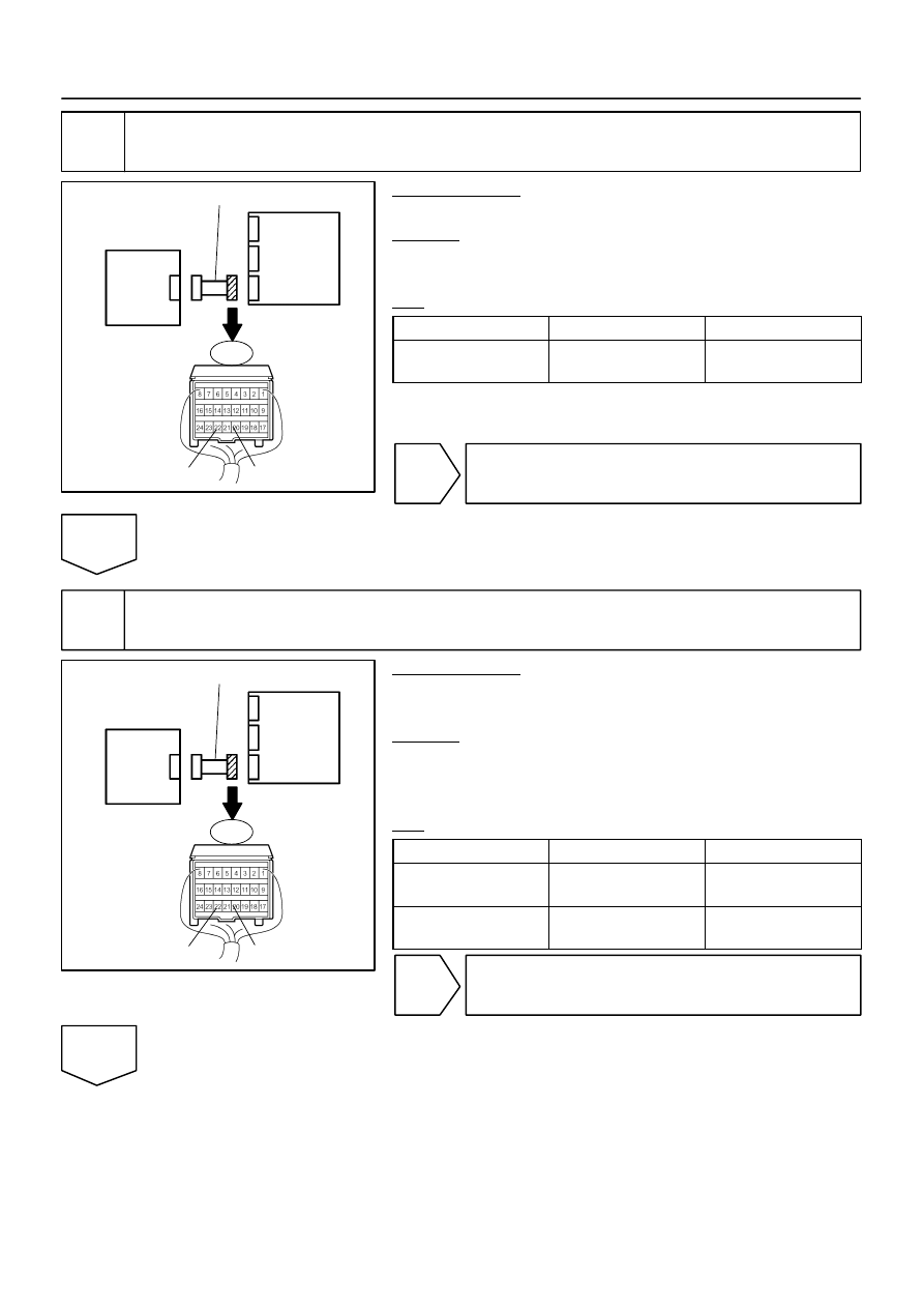
Check floor wire (short).
PREPARATION:
Disconnect the SST from connector ”C”.
CHECK:
Measure the resistance according to the value(s) in the table
below.
OK:
Tester Connection
Condition
Specified Condition
A21–22 (VUPR) –
A21–20 (ESR)
Always
1 M
Ω
or higher
NG
Repair or replace floor wire.
OK
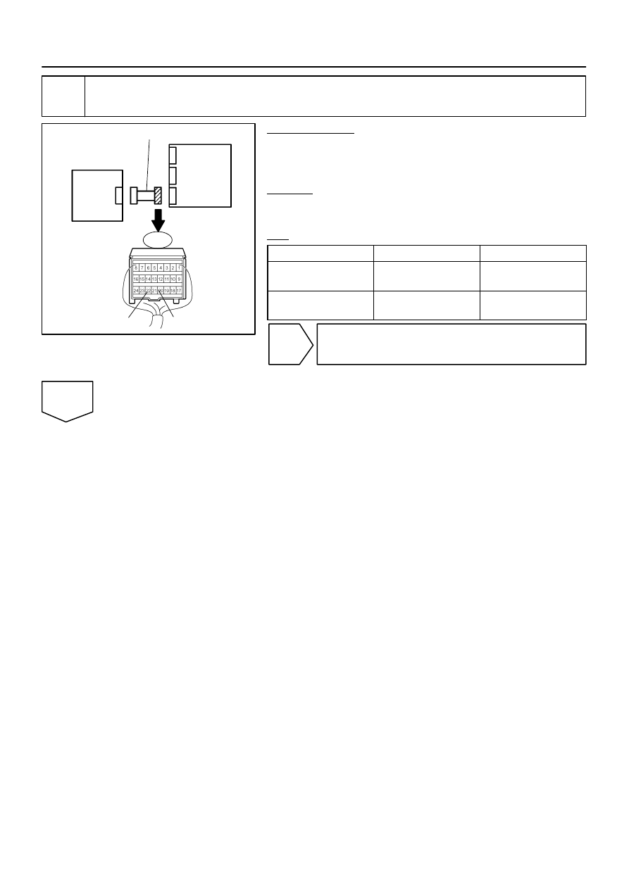
5
Check floor wire (short to B+).
PREPARATION:
Connect the negative (–) terminal cable to the battery, and wait
for at least 2 seconds.
CHECK:
(a)
Turn the ignition switch to the ON position.
(b)
Measure the voltage according to the value(s) in the table
below.
OK:
Tester Connection
Condition
Specified Condition
A21–22 (VUPR) –
Body ground
Ignition switch ON
Below 1 V
A21–20 (ESR) –
Body ground
Ignition switch ON
Below 1 V
NG
Repair or replace floor wire.
OK
H01015
G27650
H23107
Airbag
Sensor
Assembly
Side Airbag
Sensor Assembly RH
VUPR
Floor Wire
ESR
A
B
C
D
A21
DI–1184
–
DIAGNOSTICS
SUPPLEMENTAL RESTRAINT SYSTEM
1378
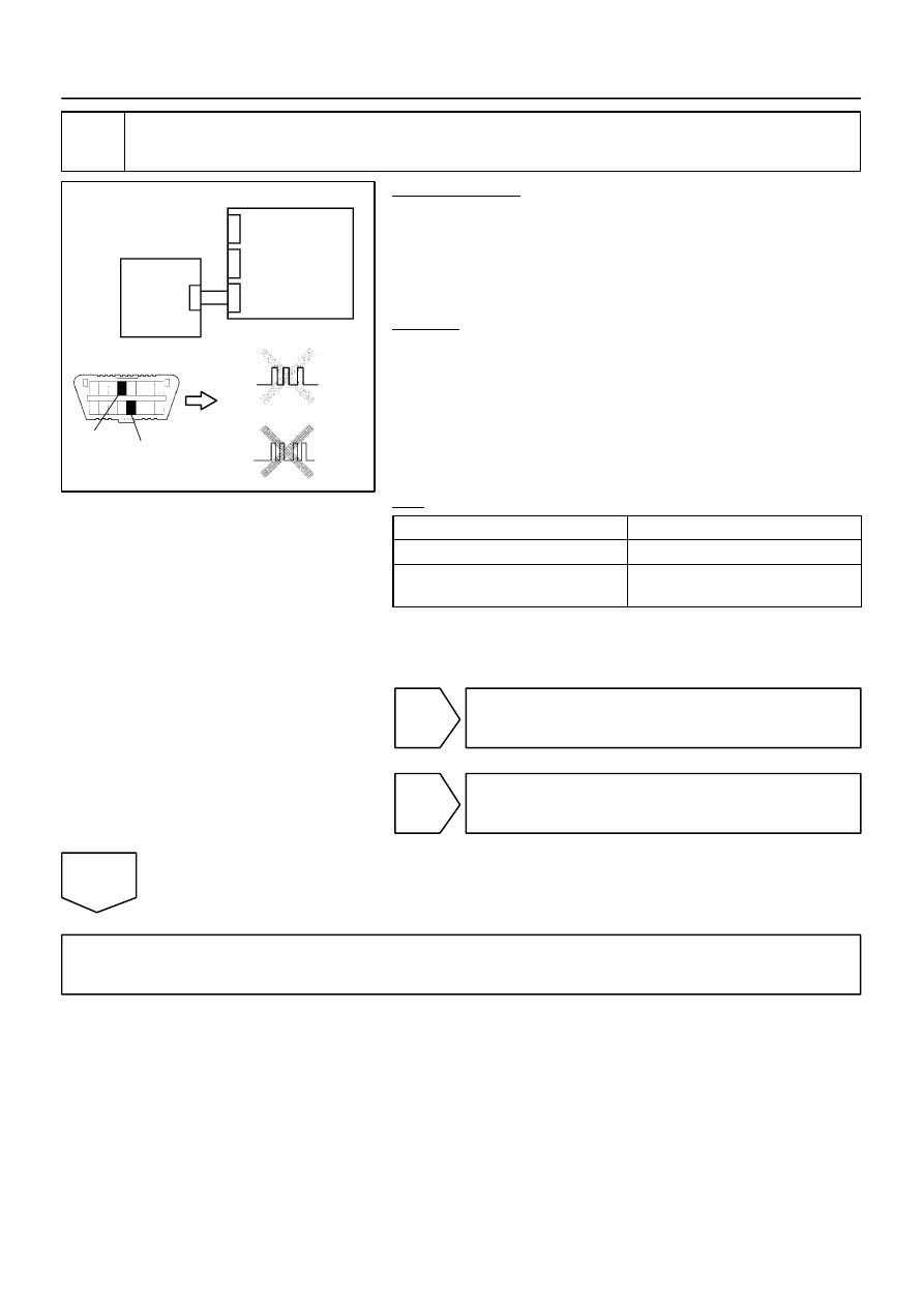
6
Check floor wire (short to ground).
PREPARATION:
(a)
Turn the ignition switch to the LOCK position.
(b)
Disconnect the negative (–) terminal cable from the bat-
tery, and wait for at least 90 seconds.
CHECK:
Measure the resistance according to the value(s) in the table
below.
OK:
Tester Connection
Condition
Specified Condition
A21–22 (VUPR) –
Body ground
Always
1 M
Ω
or higher
A21–20 (ESR) –
Body ground
Always
1 M
Ω
or higher
NG
Repair or replace floor wire.
OK
C84216
H10600
H43425
C91342
H23582
Side Airbag
Sensor Assembly LH
Airbag
Sensor
Assembly
DTC B1625/22
DTC B1620/21
CG
TC
DLC3
–
DIAGNOSTICS
SUPPLEMENTAL RESTRAINT SYSTEM
DI–1185
1379
7
Check side airbag sensor assembly RH.
PREPARATION:
(a)
Connect the connectors to the airbag sensor assembly.
(b)
Interchange the side airbag sensor assembly RH with LH
and connect the connectors to them.
(c)
Connect the negative (–) terminal cable to the battery,
and wait for at least 2 seconds.
CHECK:
(a)
Turn the ignition switch to the ON position, and wait for at
least 60 seconds.
(b)
Clear the DTCs stored in memory (see page
(c)
Turn the ignition switch to the LOCK position.
(d)
Turn the ignition switch to the ON position, and wait for at
least 60 seconds.
(e)
OK:
DTC B1620/21 is output.
A
DTC B1625/22 is output.
B
DTC B1620/21 and B1625/22 are not
output.
C
HINT:
Codes other than DTC B1620/21 and B1625/22 may be output
at this time, but they are not related to this check.
A
Replace airbag sensor assembly
(see page
).
B
Replace side airbag sensor assembly RH
(see page
).
C
From the results of the above inspection, the malfunctioning part can now be considered normal.
To make sure of this, use the simulation method to check (see page
H02751
Airbag Sensor Assembly
S15
Side Airbag Sensor Assembly LH
A19
19
VUPL
W
2
ESL
A19
21
B
1
VUPL
ESL
DI–1186
–
DIAGNOSTICS
SUPPLEMENTAL RESTRAINT SYSTEM
1380
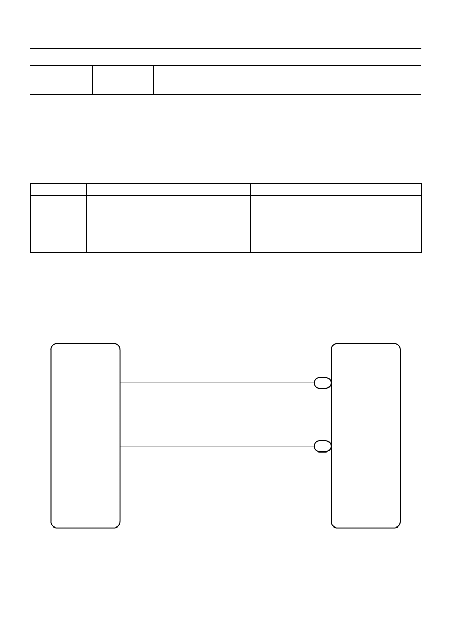
DTC
B1625/22 Side Airbag Sensor Assembly (LH)
Malfunction
CIRCUIT DESCRIPTION
The side airbag sensor assembly LH consists of the safing sensor, the diagnosis circuit, the lateral decelera-
tion sensor, etc.
If the airbag sensor assembly receives signals from the lateral deceleration sensor, it determine whether or
not the SRS should be activated.
DTC B1625/22 is recorded when a malfunction is detected in the side airbag sensor assembly LH circuit.
DTC No.
DTC Detection Condition
Trouble Area
B1625/22
The airbag sensor assembly receives a line short circuit
signal, an open circuit signal, a short circuit to ground sig-
nal or a short circuit to B+ signal in the side airbag sensor
assembly LH circuit for 2 seconds.
Side airbag sensor assembly LH malfunction
Airbag sensor assembly malfunction
Side airbag sensor assembly LH
Airbag sensor assembly
Floor wire No. 2
WIRING DIAGRAM
DIDGV–01
Нет комментариевНе стесняйтесь поделиться с нами вашим ценным мнением.
Текст