Toyota Sequoia (2005). Manual — part 42

SS0PN–07
–
SERVICE SPECIFICATIONS
CHARGING
SS–23
165
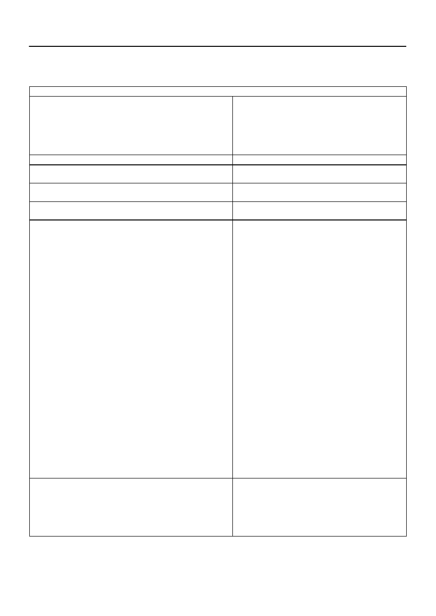
TORQUE SPECIFICATION
Part tightened
N·m
kgf·cm
ft·lbf
Bearing retainer x Drive end frame
2.6
27
23 in.·lbf
Rectifier end frame x Drive end frame
5.8
59
51 in.·lbf
Generator pulley x Rotor
110.3
1,125
81
Brush holder x Rectifier end frame
1.8
18
16 in.·lbf
Rear end cover x Rectifier end frame
4.6
47
41 in.·lbf
Generator x Cylinder block
Bolt
Nut 10 mm
Nut 8 mm
39
39
15.5
400
440
158
29
29
11
SS1M9–01
SS–24
–
SERVICE SPECIFICATIONS
AUTOMATIC TRANSMISSION (A750E, A750F)
166
AUTOMATIC TRANSMISSION (A750E, A750F)
SERVICE DATA
2UZ–FE (A750E/A750F)
Line pressure (Wheel locked)
Engine idling
D position
R position
AT stall (Throttle valve fully opened)
D position
R position
361 – 421 kPa (3.7 – 4.3 kgf
⋅
cm
2
, 52 – 61 psi)
495 – 576 kPa (5.0 – 5.9 kgf
⋅
cm
2
, 72 – 84 psi)
1,236 – 1,332kPa (12.6 – 13.6 kgf
⋅
cm
2
, 179 – 193 psi)
1,229 – 1,349 kPa (12.5 – 13.8 kgf
⋅
cm
2
, 178 – 196 psi)
Engine stall revolution
D and R positions
2,200
150 rpm
Time lag
N
→
D position
N
→
R position
Less than 1.2 seconds
Less than 1.5 seconds
Engine idle speed
(A/C OFF)
N position
700
50 rpm
Drive plate runout
Max.
Torque converter runout
Max.
0.20 mm (0.0079 in.)
0.30 mm (0.0118 in.)
Shift schedule
D position
(Throttle valve fully opened)
1
→
2
2
→
3
3
→
4
4
→
5
5
→
4
4
→
3
3
→
2
2
→
1
(Throttle valve fully closed)
4
→
5
5
→
4
4 position (O/D OFF)
(Throttle valve fully opened)
1
→
2
2
→
3
3
→
4
5
→
4
4
→
3
3
→
2
2
→
1
3 position
(Throttle valve fully opened)
1
→
2
2
→
3
4
→
3
3
→
2
2
→
1
2 position
(Throttle valve fully opened)
1
→
2
3
→
2
2
→
1
L position
(Throttle valve fully opened)
2
→
1
45 – 57 km/h (28 – 35 mph)
84 – 97 km/h (52 – 60 mph)
120 – 138 km/h (75 – 86 mph)
163 – 179 km/h (101 – 111 mph)
158 – 174 km/h (98 – 108 mph)
110 – 124 km/h (68 – 77 mph)
75 – 83 km/h (47 – 52 mph)
35 – 41 km/h (22 – 25 mph)
44 – 50 km/h (27 – 31 mph)
22 – 28 km/h (14 – 17 mph)
45 – 57 km/h (28 – 35 mph)
84 – 97 km/h (52 – 60 mph)
120 – 138 km/h (75 – 86 mph)
173 – 190 km/h (108 – 118 mph)
110 – 124 km/h (68 – 77 mph)
75 – 83 km/h (47 – 52 mph)
35 – 41 km/h (22 – 25 mph)
45 – 57 km/h (28 – 35 mph)
84 – 97 km/h (52 – 60 mph)
121 – 135 km/h (75 – 84 mph)
75 – 83 km/h (47 – 52 mph)
35 – 41 km/h (22 – 25 mph)
45 – 57 km/h (28 – 35 mph)
80 – 92 km/h (50 – 57 mph)
35 – 41 km/h (22 – 25 mph)
35 – 41 km/h (22 – 25 mph)
Lock–up point
Throttle valve opening 5 %
D position
5th gear
Lock–up ON
Lock–up OFF
4 position
4th gear
Lock–up ON
Lock–up OFF
63 – 71 km/h (39 – 44 mph)
57 – 64 km/h (35 – 40 mph)
102 – 112 km/h (63 – 70 mph)
96 – 105 km/h (60 – 65 mph)
SS1MA–01
–
SERVICE SPECIFICATIONS
AUTOMATIC TRANSMISSION (A750E, A750F)
SS–25
167
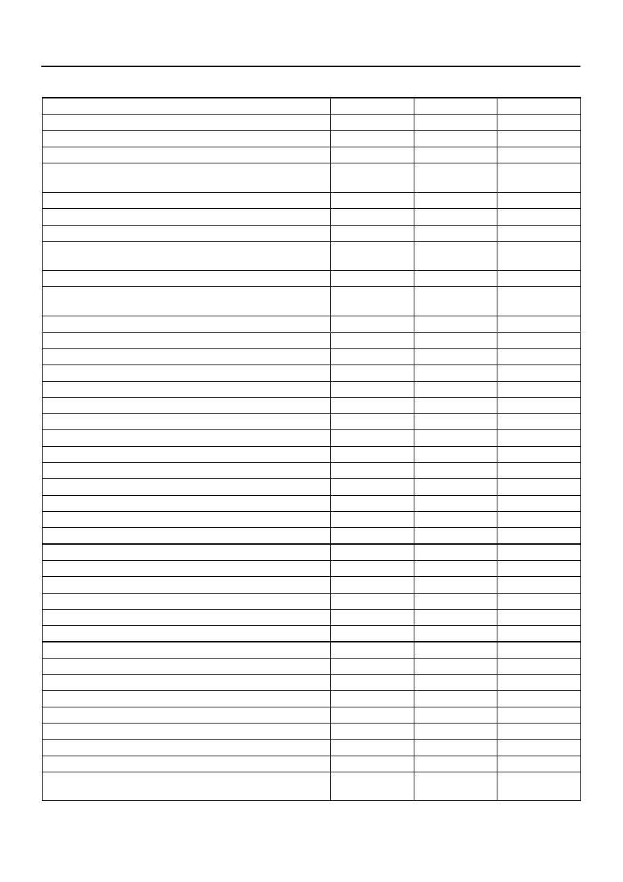
TORQUE SPECIFICATION
Part tightened
N·m
kgf·cm
ft·lbf
Drain plug x Oil pan
20
204
15
Overflow plug x Oil pan
20
204
15
Refill plug x Transmission case
39
400
29
No.1 vehicle speed sensor
A750E
A750F
9.8
11.5
100
117
86 in.
⋅
lbf
8
Speed sensor NT x Automatic transmission
5.4
55
48 in.
⋅
lbf
Speed sensor SP2 x Automatic transmission
5.4
55
48 in.
⋅
lbf
Transmission wire set bolt x Automatic transmission
5.4
55
48 in.
⋅
lbf
Transmission wire clamp x Valve body
A
B
11
10
112
100
8
7
Oil pan x Transmission case
4.4
45
39 in.
⋅
lbf
Park/neutral position switch
Bolt
Nut
13
6.9
130
70
10
61 in.
⋅
lbf
Shift solenoid valve S1 x Valve body
6.4
65
56 in.
⋅
lbf
Shift solenoid valve S2 x Valve body
10
102
7
Shift solenoid valve SR x Valve body
6.4
65
57 in.
⋅
lbf
Shift solenoid valve SLU, SL2 x Valve body
6.4
65
57 in.
⋅
lbf
Shift solenoid valve SLT, SL1 x Valve body
6.4
65
57 in.
⋅
lbf
Valve body x Transmission case
11
112
8
Oil strainer x Valve body
10
100
7
Parking lock pawl bracket x Transmission case
7.4
75
65 in.·lbf
Oil cooler x Body
11
110
8
Transmission oil cooler bracket x Oil cooler
4.9
50
43 in.·lbf
Oil cooler tube clamp x Body
5.0
50
48 in.·lbf
Shift lever x Shift lever housing
18
180
13
Shift lever housing x Steering column assemby
12
120
9
Parking lock cable No. 1 x Shift lever housing
2.9
29
25 in.·lbf
Parking lock cable No. 2 x Column upper bracket
2.2
23
19 in.·lbf
Parking lock cable housing x Steering column assembly
10.5
110
8
Front suspension member bracket x Body
33
336
24
Heat insulator
16
164
12
Shift control cable x Transmission
14.5
148
11
Shift control cable bracket x Transmission
19.5
199
14
Oil cooler pipe clamp x Transmission
12
122
9
Oil cooler pipe x Transmission
34
346
25
Stabilizer bar
37
377
27
Rear end plate x Transmission
18
185
13
Torque converter clutch x Drive plate
48
490
35
Engine rear mounting insulator x Crossmember
18
185
13
Crossmember x Frame
72
734
53
Engine rear mounting insulator x Extension housing
65
660
48
Automatic transmission x Engine
17 mm head
14 mm head
71
37
720
380
53
27

SS0PX–04
SS–26
–
SERVICE SPECIFICATIONS
TRANSFER
168
TRANSFER
SERVICE DATA
Transfer assembly
Planetary gear snap ring thickness
Mark
A
B
C
D
E
F
G
H
J
K
L
M
N
P
Q
R
S
T
U
2.10 to 2.15 mm (0.0827 to 0.0846 in.)
2.15 to 2.20 mm (0.0846 to 0.0866 in.)
2.20 to 2.25 mm (0.0866 to 0.0886 in.)
2.25 to 2.30 mm (0.0886 to 0.0906 in.)
2.30 to 2.35 mm (0.0906 to 0.0925 in.)
2.35 to 2.40 mm (0.0925 to 0.0945 in.)
2.40 to 2.45 mm (0.0945 to 0.0965 in.)
2.45 to 2.50 mm (0.0965 to 0.0984 in.)
2.50 to 2.55 mm (0.0984 to 0.1004 in.)
2.55 to 2.60 mm (0.1004 to 0.1024 in.)
2.60 to 2.65 mm (0.1024 to 0.1043 in.)
2.65 to 2.70 mm (0.1043 to 0.1063 in.)
2.70 to 2.75 mm (0.1063 to 0.1083 in.)
2.75 to 2.80 mm (0.1083 to 0.1102 in.)
2.80 to 2.85 mm (0.1102 to 0.1122 in.)
2.85 to 2.90 mm (0.1122 to 0.1142 in.)
2.90 to 2.95 mm (0.1142 to 0.1161 in.)
2.95 to 3.00 mm (0.1161 to 0.1181 in.)
3.00 to 3.05 mm (0.1181 to 0.1201 in.)
Rear output shaft
Drive sprocket thrust clearance
Standard
Maximum
Drive sprocket radial clearance
Standard
Maximum
Rear output shaft journal outer diameter
Part A
Standard
Minimum
Part B
Standard
Minimum
Part C
Standard
Minimum
Part D
Standard
Minimum
No. 1 gear shift fork claw thickness
Front drive clutch sleeve groove distance
No. 1 gear shift fork to front drive sleeve clearance
Standard
Maximum
No. 2 gear shift fork claw thickness
High and low clutch sleeve groove distance
No. 2 gear shift fork to high and low clutch sleeve clearance
Standard
Maximum
0.15 to 0.24 mm (0.0059 to 0.0094 in.)
0.24 mm (0.0094 in.)
0.01 to 0.06 mm (0.0004 to 0.0024 in.)
0.06 mm (0.0024 in.)
27.98 to 27.99 mm (1.1016 to 1.1020 in.)
27.98 mm (1.1016 in.)
31.98 to 32.00 mm (1.2591 to 1.2598 in.)
31.98 mm (1.2591 in.)
34.98 to 35.00 mm (1.3772 to 1.3780 in.)
34.98 mm (1.3772 in.)
36.98 to 37.00 mm (1.4559 to 1.4567 in.)
36.98 mm (1.4559 in.)
10 mm (0.3937 in.)
10.5 mm (0.4134 in.)
0.26 to 0.84 mm (0.0102 to 0.0331 in.)
0.84 mm (0.0331 in.)
10 mm (0.3937 in.)
10.5 mm (0.4134 in.)
0.26 to 0.84 mm (0.0102 to 0.0331 in.)
0.84 mm (0.0331 in.)
Нет комментариевНе стесняйтесь поделиться с нами вашим ценным мнением.
Текст