Toyota Sequoia (2005). Manual — part 341

–
DIAGNOSTICS
SUPPLEMENTAL RESTRAINT SYSTEM
DI–1159
1353
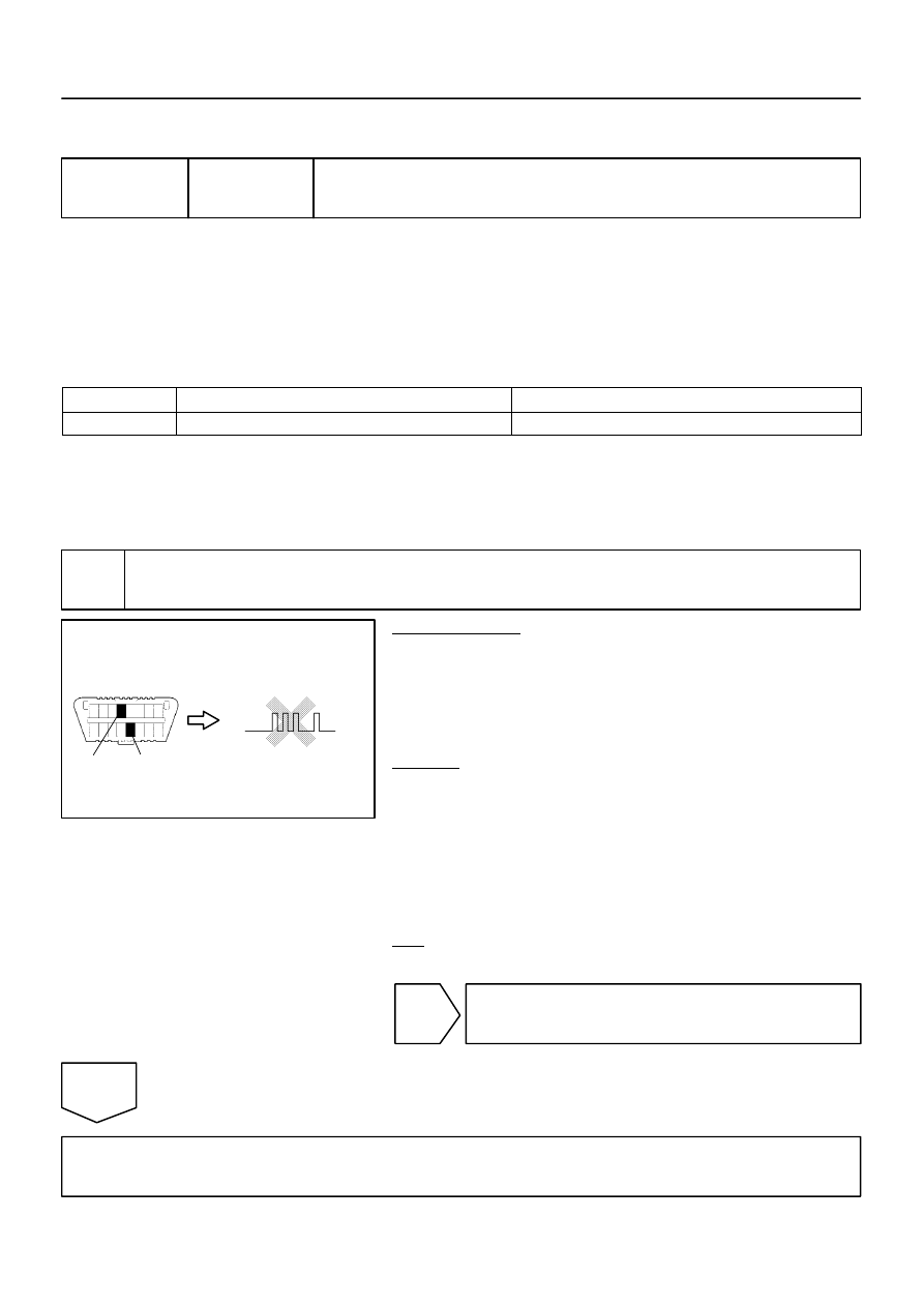
Normal
(
Source voltage drop
Battery
Airbag sensor assembly
ON
Normal
System normal
OFF
*1: w/ Side and curtain shield airbag
2.
DTCS FOR OCCUPANT CLASSIFICATION SYSTEM
If a trouble code is displayed during the DTC check, check the circuit listed for the code in the table below
(Proceed to the page listed for that circuit).
HINT:
When the DTC B1650/32 is detected as a result of troubleshooting for the Supplemental Restraint Sys-
tem, perform troubleshooting for the occupant classification system as shown in the chart below.
Use the hand–held tester to check/clear the DTC of the occupant classification ECU, otherwise the
DTC cannot be check/clear.
DTC No.
(See Page)
Detection Item
Trouble Area
Passenger Airbag
ON/OFF Indicator
B1771
)
Passenger side buckle switch circuit
malfunction
Front seat inner belt RH
Occupant classification ECU
Seat wire No. 1
ON
B1780
)
Occupant classification sensor front
LH circuit malfunction
Front seat assembly RH (Occupant classification sensor
front LH)
Occupant classification ECU
Seat wire No. 1
ON
B1781
)
Occupant classification sensor front
RH circuit malfunction
Front seat assembly RH (Occupant classification sensor
front RH)
Occupant classification ECU
Seat wire No. 1
ON
B1782
)
Occupant classification sensor rear
LH circuit malfunction
Front seat assembly RH (Occupant classification sensor
rear LH)
Occupant classification ECU
Seat wire No. 1
ON
B1783
)
Occupant classification sensor rear
RH circuit malfunction
Front seat assembly RH (Occupant classification sensor
rear RH)
Occupant classification ECU
Seat wire No. 1
ON
B1785
)
Occupant classification sensor front
LH collision detection
Front seat assembly RH (Occupant classification sensor
front LH)
Occupant classification ECU
ON
B1786
)
Occupant classification sensor front
RH collision detection
Front seat assembly RH (Occupant classification sensor
front RH)
Occupant classification ECU
ON
B1787
)
Occupant classification sensor rear
LH collision detection
Front seat assembly RH (Occupant classification sensor
rear LH)
Occupant classification ECU
ON
B1788
)
Occupant classification sensor rear
RH collision detection
Front seat assembly RH (Occupant classification sensor
rear RH)
Occupant classification ECU
ON
B1790
)
Airbag sensor assembly communica-
tion circuit malfunction
Occupant classification ECU
Airbag sensor assembly
Floor wire
Seat wire No. 1
ON
B1793
)
Occupant classification sensor power
supply circuit malfunction
Occupant classification ECU
Front seat assembly RH (Occupant classification sensors)
Seat wire No. 1
ON

DI–1160
–
DIAGNOSTICS
SUPPLEMENTAL RESTRAINT SYSTEM
1354
B1794
)
Occupant classification ECU battery
positive line open
Battery
ECU–B Fuse
Floor wire
Seat wire No. 1
Occupant classification ECU
ON
B1795
)
Occupant classification ECU circuit
malfunction
Occupant classification ECU
Seat wire No. 1
Front seat inner belt RH
ON
B1796
)
Sleep operation failure of occupant
classification ECU
Occupant classification ECU
ON
DIDGR–01
H10600
H23564
DTC B1000/31
DLC3
TC
CG
–
DIAGNOSTICS
SUPPLEMENTAL RESTRAINT SYSTEM
DI–1161
1355
CIRCUIT INSPECTION
DTC
B1000/31 Airbag Sensor Assembly Malfunction
CIRCUIT DESCRIPTION
The airbag sensor assembly consists of the airbag sensor, the safing sensor, the drive circuit, the diagnostic
circuit, ignition control, etc.
If the airbag sensor assembly receives signals from the airbag sensor, it determines whether or not the SRS
should be activated.
DTC B1000/31 is recorded when a malfunction is detected in the airbag sensor assembly.
DTC No.
DTC Detection Condition
Trouble Area
B1000/31
Airbag sensor assembly malfunction
Airbag sensor assembly
HINT:
When a trouble code is displayed simultaneously with B1000/31, repair the malfunction indicated by this
code (except B1000/31) first.
INSPECTION PROCEDURE
1
Check airbag sensor assembly.
PREPARATION:
(a)
Turn the ignition switch to the LOCK position.
(b)
Disconnect the negative (–) terminal cable from the bat-
tery, and wait for at least 90 seconds.
(c)
Connect the negative (–) terminal cable to the battery,
and wait for at least 2 seconds.
CHECK:
(a)
Turn the ignition switch to the ON position, and wait for at
least 60 seconds.
(b)
Clear the DTCs stored in memory (see page
(c)
Turn the ignition switch to the LOCK position.
(d)
Turn the ignition switch to the ON position, and wait for at
least 60 seconds.
(e)
OK:
DTC B1000/31 is not output.
NG
Replace airbag sensor assembly
(see page
).
OK
Using simulation method, reproduce malfunction symptoms (see page
).
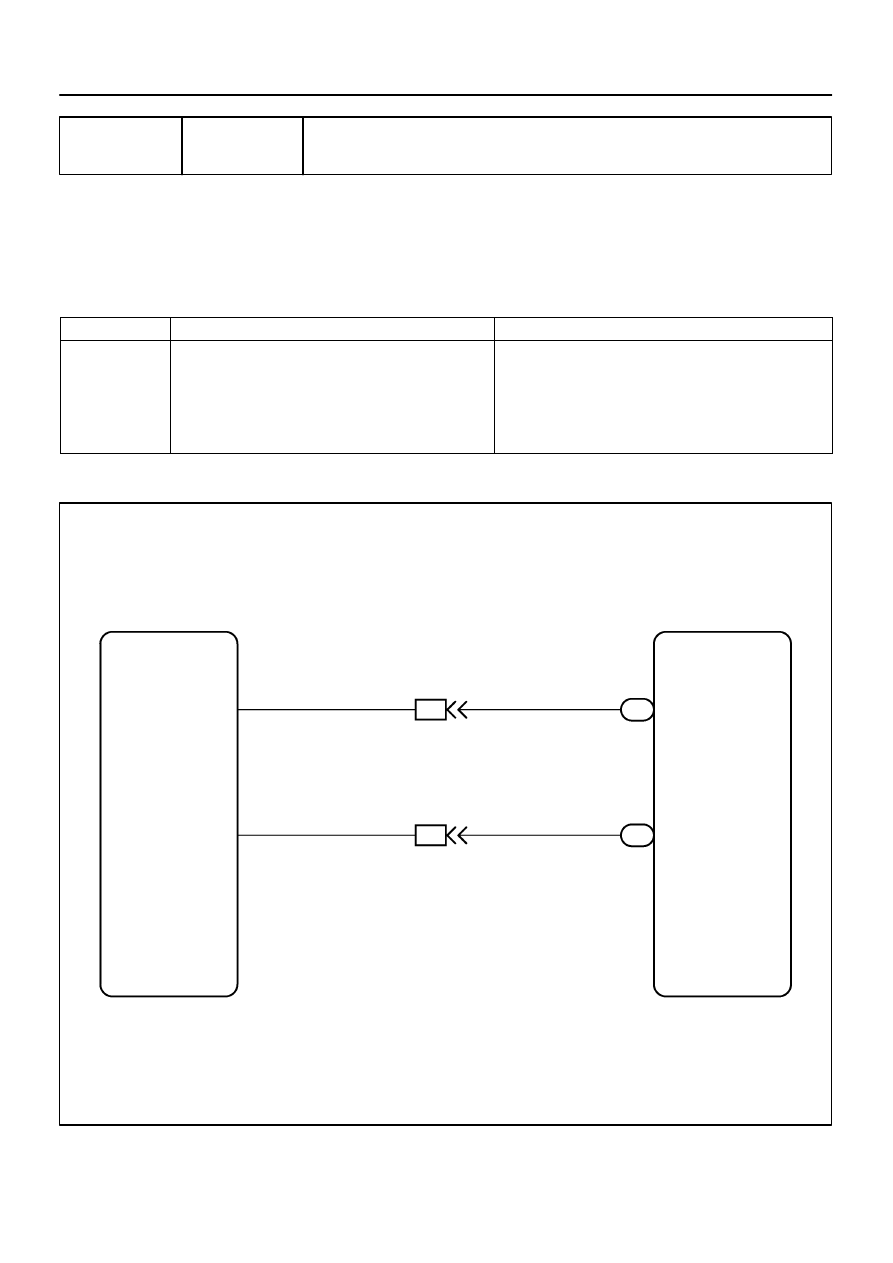
H02750
Airbag Sensor Assembly
A20 +SR
29
IL3
1
IL3
2
A20
27
A12
Front Airbag Sensor RH
2
1
–SR
W
W
B
B
+SR
–SR
DI–1162
–
DIAGNOSTICS
SUPPLEMENTAL RESTRAINT SYSTEM
1356
DTC
B1610/13 Front Airbag Sensor RH Malfunction
CIRCUIT DESCRIPTION
The front airbag sensor RH consists of the diagnosis circuit, the frontal deceleration sensor, etc.
If the airbag sensor assembly receives signals from the frontal deceleration sensor, it determines whether
or not the SRS should be activated.
DTC B1610/13 is recorded when a malfunction is detected in the front airbag sensor RH circuit.
DTC No.
DTC Detection Condition
Trouble Area
B1610/13
The airbag sensor assembly receives a line short circuit
signal, an open circuit signal, a short circuit to ground sig-
nal or a short circuit to B+ signal in the front airbag sensor
RH circuit for 2 seconds.
Front airbag sensor RH malfunction
Airbag sensor assembly malfunction
Front airbag sensor RH
Airbag sensor assembly
Cowl wire
Engine room main wire
WIRING DIAGRAM
DIDGS–01
Нет комментариевНе стесняйтесь поделиться с нами вашим ценным мнением.
Текст