Toyota Sequoia (2005). Manual — part 790
SA2CZ–01
F16823
F14100
”A”
Air tube
Housing
Connector No. 1
F14101
SST
Air tube
F14102
Plate
O–ring
Connector No.2
SST
Air tube
–
SUSPENSION AND AXLE
ELECTRONIC MODULATED AIR SUSPENSION
SA–153
3149
ELECTRONIC MODULATED AIR SUSPENSION
PRECAUTION
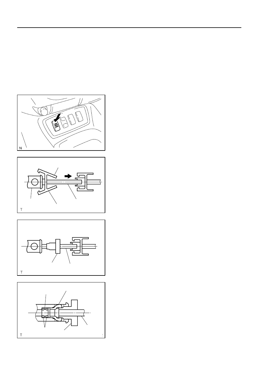
1.
WHEN LIFTING UP VEHICLE
(a)
When jacking up or lifting up, stop operation of the air sus-
pension control system by pressing the height control
mode select switch.
2.
DISCONNECTION AND CONNECTION OF HEIGHT
CONTROL TUBE
NOTICE:
Disconnection and connection of the height control
tube should be performed by hand to prevent foreign
objects from entering.
Never damage the height control tube.
(a)
Disconnect the height control tube.
(1)
Pinch ”A” of the connector No. 1 and pull out from
the housing.
(2)
Set the SST to the tube.
SST
09730–00010
(3)
Insert SST into the housing to expand the claw of
the connector No.2 in the housing.
(4)
Pull out the tube with SST inserted.
NOTICE:
Do not pull on the tube with excessive force.
F19817
O–ring
Plate
F19818
Cardboard
O–ring
Plate
F19819
Connector No.2
F14103
Housing
Claw
Connector No. 1
Air tube
Port (Hole)
SA–154
–
SUSPENSION AND AXLE
ELECTRONIC MODULATED AIR SUSPENSION
3150
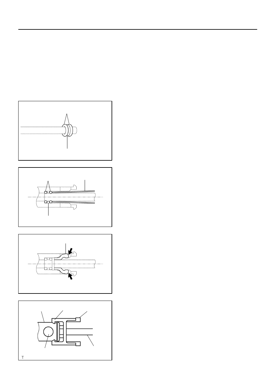
(5)
Insert a screwdriver into the circular hole on the
housing, and remove the connector No.2, the 2 O–
rings and the plate from the housing.
HINT:
The O–rings, plate and connector No.2 are non–reusable parts.
(b)
Install 2 O–rings and the plate.
(1)
Apply MP grease to 2 new O–rings and plate and
install them to the straight tube or an equivalent.
NOTICE:
Install the plate between the O–rings.
Keep foreign matter from adhering to the O–rings and the
height control tube in order to prevent air leaks.
(2)
Insert the tube on which the 2 O–rings and plate are
installed into the housing, and then push it in lightly
with a piece of rolled up cardboard.
(3)
Push the connector No.2 into the housing to where
a clicking sound is heard.
(c)
Install the height control tube.
(1)
Push the tube and connector No.1 into the housing
to where a clicking sound is heard.
NOTICE:
The port (hole) of the housing should be set in the
position 90
°
from the claws of connector No. 1.
Pull the tube lightly to make sure that it is securely
connected.
–
SUSPENSION AND AXLE
ELECTRONIC MODULATED AIR SUSPENSION
SA–155
3151
Prevent foreign matter from being attached to the O–
rings and height control tube. Failure to do so may
cause air leakage.
SA2D0–01
F16824
HIGH
NORMAL
LOW
SA–156
–
SUSPENSION AND AXLE
ELECTRONIC MODULATED AIR SUSPENSION
3152
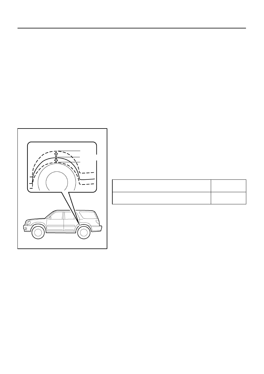
ADJUSTMENT
1.
ADJUST STANDARD VEHICLE HEIGHT
(a)
Release the parking brake and stabilize the suspensions by pushing up and down on the corners of
the vehicle.
(b)
Place the shift lever into the ”N” position and settle the tires by moving the vehicle back and forth.
(c)
Start the engine.
(d)
On the height control switch, first press ”HIGH” to raise the vehicle height, and then change the switch
to ”LOW” to lower it. Perform this operation one more time.
NOTICE:
Make sure to release the parking brake and move the shift lever into the ”N” position.
2.
INSPECT TIRE (See page
3.
MEASURE VEHICLE HEIGHT (See page
4.
OPERATE HEIGHT CONTROL SWITCH AND CHECK
VEHICLE HEIGHT CHANGE
(a)
Start the engine and change the height control switch
from the NORMAL position to the HIGH and LOW posi-
tions.
Check the time until the height adjustment is completed
and the amount of change in vehicle height.
Adjustment time
From operation of height control switch
to start of compressor.
Approx. 2 sec.
From start of compressor to completion
of height adjustment.
Approx. 20 sec.
Amount of change in vehicle height
HIGH position: 40 mm (1.57 in.)
LOW position:
4WD models: –30 mm (–1.18 in.)
2WD models: –15 mm (–0.59 in.)
Нет комментариевНе стесняйтесь поделиться с нами вашим ценным мнением.
Текст