Toyota Sequoia (2005). Manual — part 226

–
DIAGNOSTICS
AIR SUSPENSION SYSTEM
DI–699
893
Input and output signals of each ECU.
Transmitting ECU
Receiving ECU
Signal
Communication method
ECM
Translate ECU
Suspension control
ECU
Engine speed signal
Transmission signal
Shift position signal
L4 switch signal
TC signal
CAN
Translate ECU
Suspension control
ECU
Vehicle wheel speed signal
TS signal
CAN
Suspension control ECU
Translate ECU
Air suspension setting signal
CAN
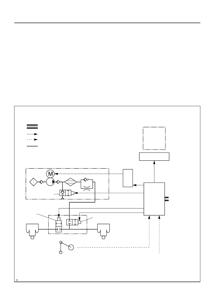
DIDCN–01
F19465
: CAN
Compressor Assy
Combination Meter
Suspension
Control
ECU
Exhaust Solenoid
Valve
Gate Solenoid Valve
Leveling Solenoid Valve
AIR SUS Relay
Height Control Cylinder
(Pneumatic Cylinder)
Height Control Sensor
Sub–assy
: ECU Output Signal
: ECU Input Signal
: Air Flow Path
Dryer
Height Control Cylinder
(Pneumatic Cylinder)
Speed Sensors
Engine Speed
L4 Switch
Shift Position
Information
Transmission
Model Informa-
tion
Height Control Mode Select
Switch
Height Control Switch
Courtesy Light Switches
Stop Light Switch
HI
N
LO
MAN.
DI–700
–
DIAGNOSTICS
AIR SUSPENSION SYSTEM
894
SYSTEM DESCRIPTION
1.
GENERAL
This system uses pneumatic cylinders instead of the coil springs that are used in a conventional rear
suspension. The suspension control ECU analyzes the information based on the switches, sensors,
and input signals, operates the compressor assy, and uses the solenoid valves to control the vehicle
height.
The suspension control ECU detects, via the height control sensor, the changes in the rear vehicle
height that results from the number of occupants or the amount of the load. Then, the suspension con-
trol ECU controls the height control solenoid valves and the compressor assy in order to automatically
adjust the rear vehicle height to a constant (normal) vehicle height.
Furthermore, three vehicle heights can be selected by operating the height control switch: HI, NOR-
MAL, and LO. The HI vehicle height ensures the vehicle’s drive–through performance on rough roads.
The LO vehicle height facilitates the entry and exit of the occupants and the loading and unloading
of cargo. The NORMAL vehicle height helps realize excellent controllability and riding comfort during
normal driving.
–
DIAGNOSTICS
AIR SUSPENSION SYSTEM
DI–701
895
2.
REAR AIR SUSPENSION SYSTEM DESCRIPTION
(a)
Auto leveling function
The function to keep the rear vehicle height fixed regardless of the change in the number of the occupants
or the load.
(b)
Vehicle height control function
(1)
Mode change:
The mode can be changed between the auto mode and the manual mode by operating the
height control mode select switch.
Vehicle height control can be canceled by changing the height control mode select switch
to manual mode.
(2)
Auto mode:
Vehicle height can be set to NORMAL, HIGH (+40 mm (1.57 in.)) or LOW (4WD: –30 mm
(–1.18 in.), 2WD: –15 mm (–0.59 in.)) by operating the height control switch.
When vehicle speed is 12 km/h (7.46 mph) or less, vehicle height is LOW.
When vehicle speed is 30 km/h (18.64 mph) or less, vehicle height is HIGH.
(3)
Manual mode:
Vehicle height can be set in any level within the vehicle height adjustable range by operat-
ing the height control switch.
Vehicle speed is 30 km/h (18.64 mph) or less.
(4)
Adjusting time:
Approximately 20 seconds is needed to adjust vehicle height to UP (+40 mm (1.57 in.)).
Approximately 30 seconds is needed to adjust vehicle height to DOWN (–40 mm (–1.18
in.)).
(c)
Vehicle speed detection function
When any of the following conditions are met with the vehicle height set to any position other than
NORMAL, vehicle height is automatically adjusted to NORMAL.
AUTO MODE: When vehicle speed is 12 km/h (7.46 mph) or less, vehicle height is LOW.
AUTO MODE: When vehicle speed is 30 km/h (18.64 mph) or less, vehicle height is HIGH.
MANUAL MODE: Vehicle speed is 30 km/h (18.64 mph) or less.
(d)
Vehicle height adjustment control after turning the ignition switch off
If the rear vehicle height is raised after the ignition switch is turned off, such as when the occupant gets out
of the vehicle, vehicle height is lowered to the correct position for several seconds even after the ignition
switch is turned off.
(e)
Fail–safe
If the vehicle control switch is operated frequently to change vehicle height, vehicle height control is sus-
pended for a while to prevent the compressor from becoming overheated.
DI–702
–
DIAGNOSTICS
AIR SUSPENSION SYSTEM
896
3.
FUNCTION OF MAIN COMPONENTS
Component
Outline
Height Control Mode Select Switch
Used to select vehicle height control mode (Auto/Manual).
Used to operate or stop auto leveling control.
Height Control Switch
Auto mode: Used to select vehicle height (HIGH, NORMAL, LOW).
Manual mode: Used to select vehicle height optionally.
Height Control Sensor
Converts the vertical change of the rear axle, in proportion to the standard, to sig-
nals and detects vehicle height.
Height Control Indicator Lamp (Combination Meter)
Auto mode: Target vehicle height is displayed (HIGH, NORMAL, LOW).
Manual mode: Current vehicle height is displayed (HIGH, NORMAL, LOW).
Height Control Manual Indicator Lamp (Combination Meter)
Comes on during manual mode.
Blinks when the suspension control ECU detects a system malfunction.
Blinks during test mode.
Displays output DTC.
Stop light Switch
Detects braking condition.
Used to clear DTCs.
Pneumatic Cylinder (Height Control Cylinder Assy)
Supports the vehicle body and adjusts the vehicle height.
Height Control Compressor Assy (Compressor/Height Con-
trol Dryer)
The compressor generates compressed air that is necessary to raise vehicle
height and supplies it to the height control cylinder assy.
The dryer removes moisture from the compressed air.
Exhaust Solenoid Valve
Drains the air in the height control cylinder assy when vehicle height is lowered.
(Built into the height control compressor assy)
Leveling Solenoid Valve
Opens or closes the passage between the height cylinder assy and height control
compressor assy.
Gate Solenoid Valve
Opens or closes the passage between the right and left height control cylinder assy
(Built into the leveling solenoid valve).
Suspension Control ECU
Estimates vehicle condition based on the signals from sensors and switches, and
outputs the control signals to the compressor and valves.
Blinks the height control manual indicator light when a system malfunction is de-
tected.
Air Suspension Relay
Supplies power to the height control compressor assy.
Door Courtesy Switch (Body ECU)
Detects whether the 5 doors, including the back door, are opened or closed, and
sends the signals to the suspension control ECU.
ECM
Sends the engine speed signal, etc. to the suspension control ECU through CAN
communication.
Speed Sensor (Skid Control ECU)
Sends the vehicle wheel speed signal, etc. to the suspension control ECU through
CAN communication via the translate ECU.
Нет комментариевНе стесняйтесь поделиться с нами вашим ценным мнением.
Текст