Toyota Sequoia (2005). Manual — part 428
DIDE2–01
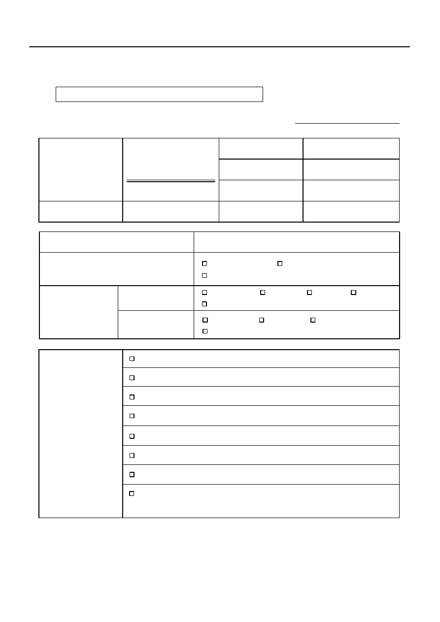
Inspector’s Name:
Customer’s Name
Production Date
VIN
Licence Plate No.
Odometer Reading
/ /
/ /
Frequency Problem Occurs
/ /
Constant
Intermittent ( times a day)
km
miles
All functions do not operate.
Weather Conditions
When Problem
Occurred
Weather
Outdoor
Temperature
Only once
Fine
Various/Others
Cloudy
Rainy
Snowy
Hot
Cold (
C (
F))
Warm
Cool
Problem Symptoms
Sliding function does not operate.
Reclining function does not operate.
Front vertical function does not operate.
Lifter function does not operate.
Seat position memory function does not operate.
Others
POWER SEAT CONTROL SYSTEM Check Sheet
Lumbar support function does not operate.
–
DIAGNOSTICS
POWER SEAT CONTROL SYSTEM (w/ Driving Position
Memory)
DI–1507
1701
CUSTOMER PROBLEM ANALYSIS CHECK
DIDE4–01
DI–1508
–
DIAGNOSTICS
POWER SEAT CONTROL SYSTEM (w/ Driving Position
Memory)
1702
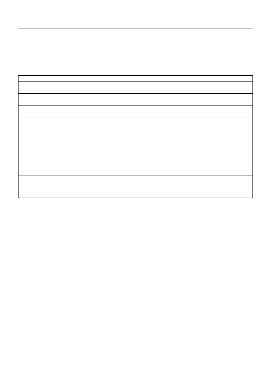
PROBLEM SYMPTOMS TABLE
HINT:
If the cause of the problem still cannot be determined after the corresponding inspection, proceed to
the next step shown in this table.
The system uses multiplex communication. Check for DTCs for the multiplex communication system
before performing the following inspection.
Symptom
Suspected Area
See Page
Power seat does not operate (manual or memorized positions).
1. Power source circuit
2. Position control ECU & switch assy
One function of power seat does not operate (manual or memo-
rized positions).
1. Power seat motor circuit
2. Position control ECU & switch assy
One or all manual seat functions do not operate (memorized
positions OK).
Position control ECU & switch assy
Memory function does not operate.
1. Power source circuit
2. Power seat memory switch circuit
3. Park/neutral position switch circuit
4. Door courtesy switch circuit
5. Position control ECU & switch assy
All memory functions do not operate or operate a little then stop
(manual functions OK).
1. Power source circuit
2. Position control ECU & switch assy
One memory function does not operate or operates a little then
stops (manual functions OK).
1. Power seat motor circuit
2. Position control ECU & switch assy
Lumbar support does not operate.
Lumbar support control switch circuit
The power seat control system does not control the storing and
restoring of the power mirror position.
1. Multiplex communication system
2. Driving position memory switch
3. Outer mirror assy
4. Position control ECU & switch assy
DIDE5–01
I27716
M7
M6
–
DIAGNOSTICS
POWER SEAT CONTROL SYSTEM (w/ Driving Position
Memory)
DI–1509
1703
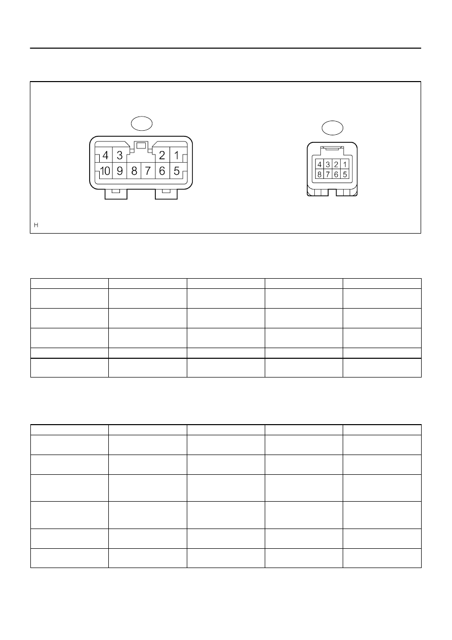
TERMINALS OF ECU
1.
CHECK POSITION CONTROL ECU & SWITCH ASSY
(a)
Disconnect the M6 and M7 ECU & switch connectors.
(b)
Check the voltage of each terminal of the wire harness side connectors.
Standard:
Symbols (Terminal No.)
Wiring Color
Terminal Description
Condition
Specified Condition
GND (M7–1) –
Body ground
W–B – Body ground
Ground
Always
Below 1 V
+B (M7–5) –
GND (M7–1)
L–O – W–B
Battery
Always
10 to 14 V
SYSB (M6–8) –
GND (M7–1)
W–R – W–B
Power source
Always
10 to 14 V
IG (M6–4) – GND (M7–1)
B–R – W–B
Ignition switch
Ignition switch OFF
→
ON
Below 1 V
→
10 to 14 V
MPX1 (M6–1) –
GND (M7–1)
W – W–B
Communication signal
Always
10 k
Ω
or higher
If the result is not as specified, there may be a malfunction on the wire harness side.
(c)
Reconnect the M6 and M7 ECU & switch connectors.
(d)
Check the voltage of each terminal of the connectors.
Standard:
Symbols (Terminal No.)
Wiring Color
Terminal Description
Condition
Specified Condition
SLD+ (M7–2) –
GND (M7–1)
L – W–B
Sliding motor signal
(Forward)
Seat moving forward using
sliding switch
→
Others
10 to 14 V
→
Below 1 V
SLD– (M7–3) –
GND (M7–1)
Y – W–B
Sliding motor signal
(Rearward)
Seat moving rearward us-
ing sliding switch
→
Others
10 to 14 V
→
Below 1 V
FRV+ (M7–6) –
GND (M7–1)
G – W–B
Front vertical motor signal
(Upward)
Seat cushion front portion
raising using front vertical
switch
→
Others
10 to 14 V
→
Below 1 V
FRV– (M7–4) –
GND (M7–1)
B – W–B
Front vertical motor signal
(Downward)
Seat cushion front portion
lowering using front vertical
switch
→
Others
10 to 14 V
→
Below 1 V
LFT+ (M7–7) –
GND (M7–1)
W – W–B
Lifter motor signal
(Upward)
Seat raising using lifter
switch
→
Others
10 to 14 V
→
Below 1 V
LFT– (M7–9) –
GND (M7–1)
V – W–B
Lifter motor signal
(Downward)
Seat lowering using lifter
switch
→
Others
10 to 14 V
→
Below 1 V

DI–1510
–
DIAGNOSTICS
POWER SEAT CONTROL SYSTEM (w/ Driving Position
Memory)
1704
RCL+ (M7–8) –
GND (M7–1)
P – W–B
Reclining motor signal
(Forward)
Seat back moving forward
using reclining switch
→
Others
10 to 14 V
→
Below 1 V
RCL– (M7–10) –
GND (M7–1)
BR – W–B
Reclining motor signal
(Rearward)
Seat back moving rear-
ward using reclining switch
→
Others
10 to 14 V
→
Below 1 V
If the result is not as specified, the position control ECU & switch assy may be malfunctioning.
Нет комментариевНе стесняйтесь поделиться с нами вашим ценным мнением.
Текст