Toyota Sequoia (2005). Manual — part 1
IN01O–10
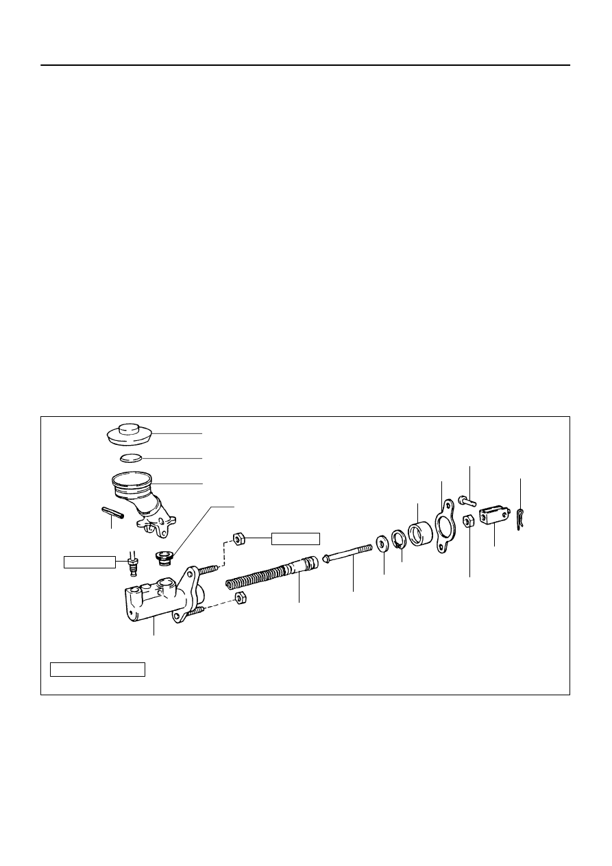
N17080
Filler Cap
Float
Reservoir Tank
Grommet
Clip
Slotted Spring Pin
: Specified torque
Non–reusable part
Cylinder
Piston
Push Rod
Washer
Snap Ring
Boot
Gasket
Lock Nut
Clevis Pin
Clevis
N·m (kgf·cm, ft·lbf)
12 (120, 9)
15 (155, 11)
–
INTRODUCTION
HOW TO USE THIS MANUAL
IN–1
1
HOW TO USE THIS MANUAL
GENERAL INFORMATION
1.
INDEX
An INDEX is provided on the first page of each section to guide you to the item to be repaired. To assist you
in finding your way through the manual, the Section Title and major heading are given at the top of every
page.
2.
GENERAL DESCRIPTION
At the beginning of each section, a General Description that pertains to all repair operations contained in
that section is given.
Read these precautions before starting any repair task.
3.
TROUBLESHOOTING
TROUBLESHOOTING tables are included for each system to help you diagnose the problem and find the
cause. The fundamentals of how to proceed with troubleshooting are described on page
.
Be sure to read this before performing troubleshooting.
4.
PREPARATION
Preparation lists the SST (Special Service Tools), recommended tools, equipment, lubricant and SSM (Spe-
cial Service Materials) which should be prepared before beginning the operation and explains the purpose
of each one.
5.
REPAIR PROCEDURES
Most repair operations begin with an overview illustration. It identifies the components and shows how the
parts fit together.
Example:
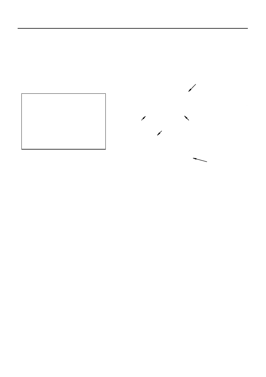
Illustration:
what to do and where to do
21. CHECK PISTON STROKE OF OVERDRIVE BRAKE
(a)
Task heading : what to do
SST 09350–30020 (09350–06120)
Set part No.
Component part No.
Detailed text :
how to do task
(b)
Piston stroke: 1.40
1.70 mm (0.0551
0.0669 in.)
Specification
Place SST and a dial indicator onto the overdrive brake pis-
ton as shown in the illustration.
Measure the stroke applying and releasing the compressed
air (392
785 kPa, 4 8
kgf/cm
2
or 57
114 psi) as shown
in the illustration.
IN–2
–
INTRODUCTION
HOW TO USE THIS MANUAL
2
The procedures are presented in a step–by–step format:
The illustration shows what to do and where to do.
The task heading tells what to do.
The detailed text tells how to perform the task and gives other information such as specifications
and warnings.
Example:
This format provides the experienced technician with a FAST TRACK to the information needed. The upper
case task heading can be read at a glance when necessary, and the text below it provides detailed informa-
tion. Important specifications and warnings always stand out in bold type.
6.
REFERENCES
References have been kept to a minimum. However, when they are required, you are given the page to refer
to.
7.
SPECIFICATIONS
Specifications are presented in bold type throughout the text where needed. You never have to leave the
procedure to look up your specifications. They are also found in Service Specifications section for quick ref-
erence.
8.
CAUTIONS, NOTICES, HINTS:
CAUTIONS are presented in bold type, and indicate there is a possibility of injury to you or other
people.
NOTICES are also presented in bold type, and indicate the possibility of damage to the components
being repaired.
HINTS are separated from the text but do not appear in bold. They provide additional information to
help you perform the repair efficiently.
9.
SI UNIT
The UNITS given in this manual are primarily expressed according to the SI UNIT (International System of
Unit), and alternately expressed in the metric system and in the English System.
Example:
Torque: 30 N·m (310 kgf·cm, 22 ft·lbf)
IN0IF–02
B04769
A
B
B04198
2UZ–FE Engine:
–
INTRODUCTION
IDENTIFICATION INFORMATION
IN–3
3
IDENTIFICATION INFORMATION
VEHICLE IDENTIFICATION AND
ENGINE SERIAL NUMBER
1.
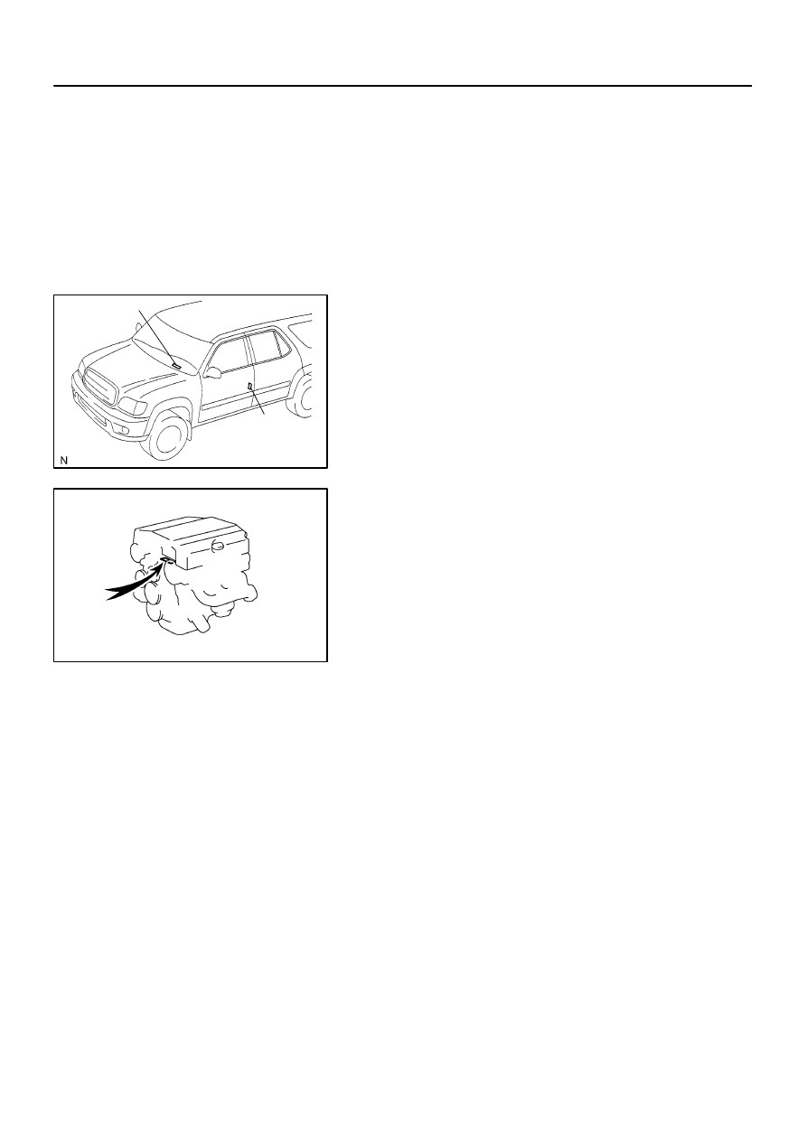
VEHICLE IDENTIFICATION NUMBER
The vehicle identification number is stamped on the vehicle
identification number plate and certification label.
A: Vehicle Identification Number Plate
B: Certification Label
2.
ENGINE SERIAL NUMBER
The engine serial number is stamped on the engine block, as
shown in the illustration.
FI1066
IN0D9–03
Z11554
Seal Lock Adhesive
IN–4
–
INTRODUCTION
REPAIR INSTRUCTIONS
4
REPAIR INSTRUCTIONS
GENERAL INFORMATION
BASIC REPAIR HINT
(a)
Prevent damage and maintain vehicle cleanliness by pro-
tective covering on the fender, seat and floor.
(b)
During disassembly, keep parts in the appropriate order
to facilitate reassembly.
(c)
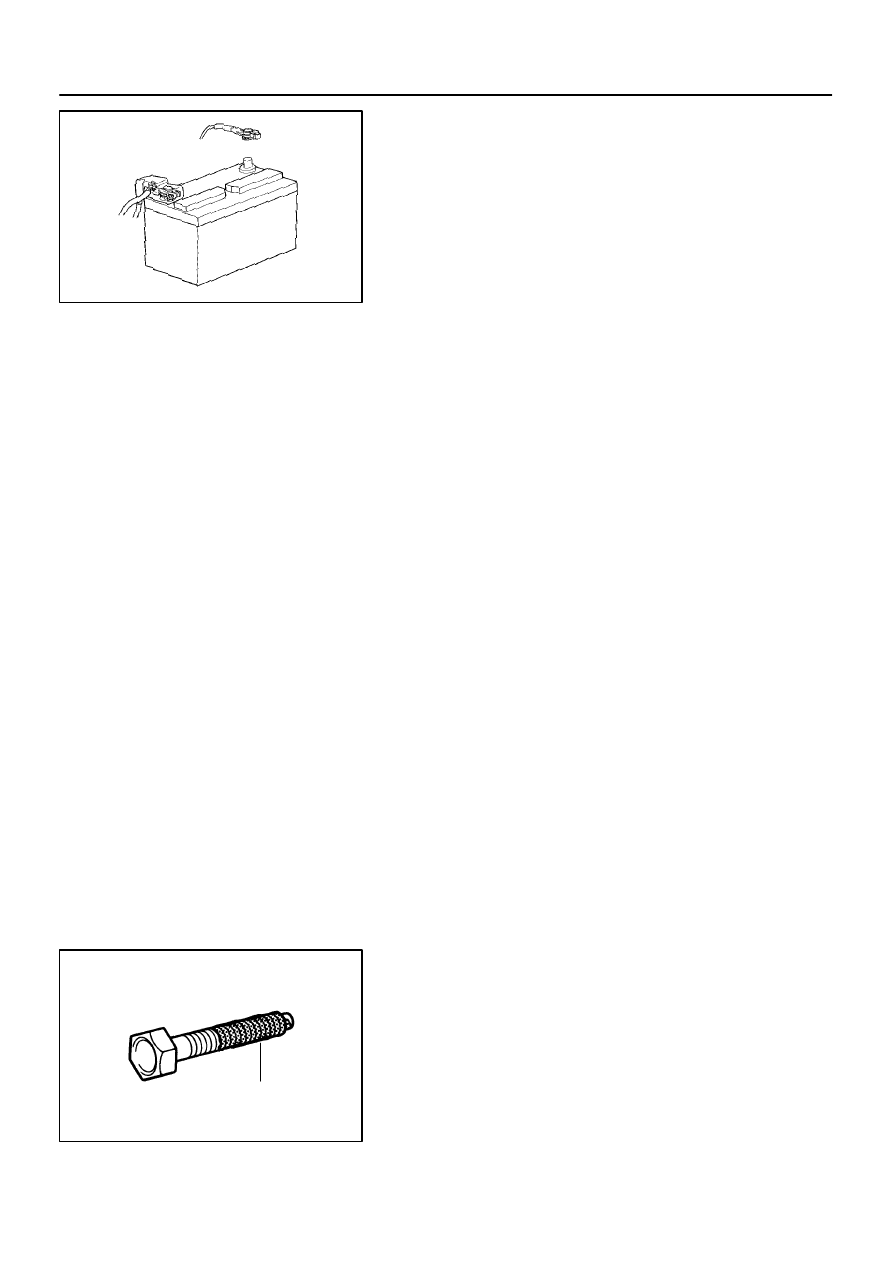
Installation and removal of battery terminal:
(1)
Before performing electrical work, disconnect the
negative (–) terminal cable from the battery.
(2)
If it is necessary to disconnect the battery for in-
spection or repair, first disconnect the negative (–)
terminal cable.
(3)
When disconnecting the terminal cable, to prevent
damage to battery terminal, loosen the cable nut
and raise the cable straight up without twisting or
prying it.
(4)
Clean the battery terminals and cable ends with a
clean shop rag. Do not scrape them with a file or oth-
er abrasive objects.
(5)
Install the cable ends to the battery terminals after
loosening the nut and tighten the nut. Do not use a
hammer to tap the cable ends onto the terminals.
(6)
Be sure the cover for the positive (+) terminal is
properly in place.
(d)
Check hose and wiring connectors to make sure that they
are connected securely and correctly.
(e)
Non–reusable parts
(1)
Always replace cotter pins, gaskets, O–rings, oil
seals, etc. with new ones.
(2)
Non–reusable parts are indicated in the component
illustrations by the ”
” symbol.
(f)
Precoated parts
Precoated parts are bolts, nuts, etc. that are coated with
a seal lock adhesive at the factory.
(1)
If a precoated part is retightened, loosened or
caused to move in any way, it must be recoated with
the specified adhesive.
(2)
When reusing precoated parts, clean off the old
adhesive and dry with compressed air. Then apply
the specified seal lock adhesive to the bolt, nut or
threads.
Нет комментариевНе стесняйтесь поделиться с нами вашим ценным мнением.
Текст