Toyota Sequoia (2005). Manual — part 314
–
DIAGNOSTICS
ABS WITH EBD & BA & TRAC & VSC SYSTEM
DI–1051
1245
3
Check for open and short circuit in harness and connector between terminal
CSW of the translate ECU and center diff. lock (TRAC OFF) switch and body
ground (See page
).
NG
Repair or replace harness or connector.
OK
4
Check VSC OFF (TRAC OFF) indicator light.
See combination meter troubleshooting on page
NG
Repair or replace combination meter
(See page
OK
5
Check for open and short circuit in harness and connector between terminal WT
of the translate ECU and VSC OFF (TRAC OFF) indicator light (See page
NG
Repair or replace harness or connector.
OK
Check and replace translate ECU
F19781
Translate ECU
O
J43
J/C
O
A
A
8
5
B
F10
Fusible
Link
Block
ALT
W–B
40
T5
GND
A
A
J18
J/C
W–B
W–B
W–B
IL1
1
S1
32
S1
9
IL1
GND1
GND2
Battery
IG
IG
ABS & VSC Actuator
(Skid Control ECU)
VSC+
VSC–
IG1
CANH
CANL
BZ
17
L
T5
11
T5
1
T5
6
S1
2
S1
22
S1
IL2
7
IL2
6
IL1
15
W
L
W
B–R
B–R
B–R
W–L
W–L
B–R
B–R
W
W–L
B–Y
W
V5
VSC Warning Buzzer
Buzzer
J37
A
J38
A
J37
A
3C
8
3A
8
1F
4
1L
1
1C
4
6
1C
I18
Ignition SW
1
2
AM1
IG1
AM1
ECU–IG
Sub J/B No.3
Instrument Panel J/B
2
1
1
2
O
7
J/C
(*) CAN1 Circuit
(*)
(*)
(*)
(*)
DI–1052
–
DIAGNOSTICS
ABS WITH EBD & BA & TRAC & VSC SYSTEM
1246
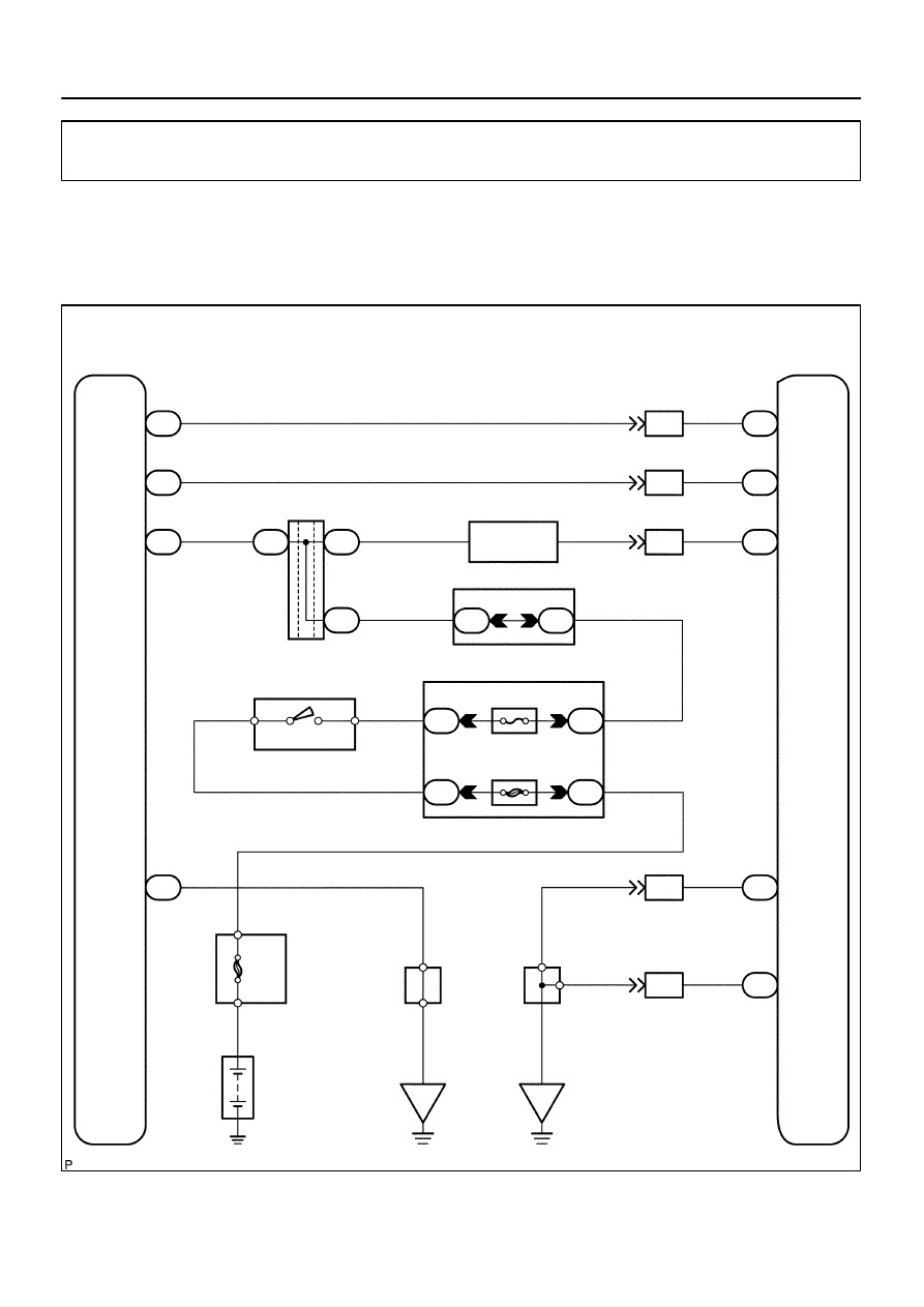
VSC Buzzer Circuit
CIRCUIT DESCRIPTION
The VSC buzzer sounds during VSC operation.
WIRING DIAGRAM
DI949–03
–
DIAGNOSTICS
ABS WITH EBD & BA & TRAC & VSC SYSTEM
DI–1053
1247
INSPECTION PROCEDURE
HINT:
Start the inspection from step 1 when using the hand–held tester and start from step 2 when not using the
hand–held tester.
1
Check operation of the VSC buzzer.
PREPARATION:
(a)
Connect the hand–held tester to the DLC3.
(b)
Turn the ignition switch to the ON position and push the hand–held tester main switch ON.
(c)
Select ACTIVE TEST mode on the hand–held tester.
CHECK:
Check ”ON–OFF” function of the VSC buzzer with the hand–held tester.
Item
Vehicle Condition / Test Details
Diagnostic Note
VSC / BR WARN BUZ
Turns VSC / BRAKE warning buzzer ON / OFF
Buzzer can be heard
OK:
Buzzer sound can be heard.
OK
Replace skid control ECU
(See page
NOTICE:
When replacing the skid control ECU, perform the zero
point calibration (See page
NG
2
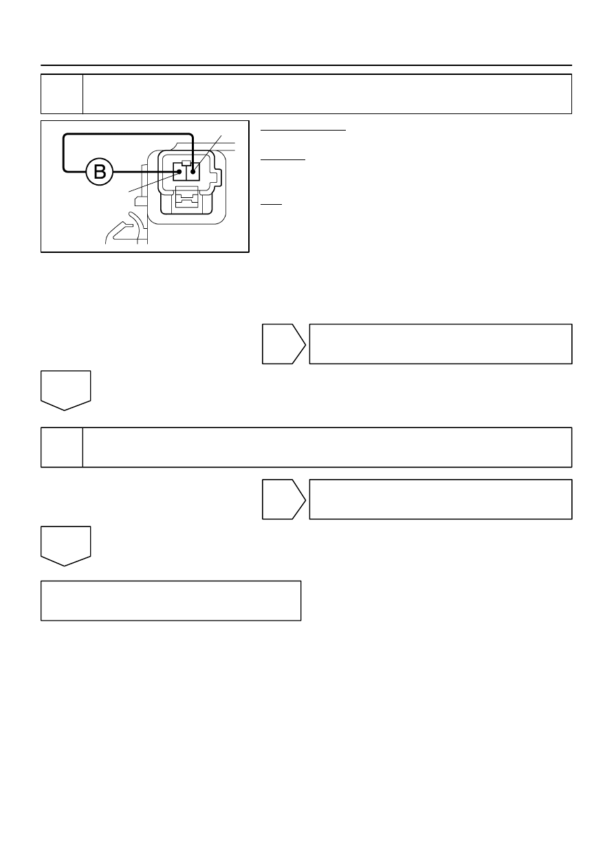
Check voltage between terminal 2 of the VSC buzzer and body ground.
PREPARATION:
Remove the VSC buzzer with connectors still connected.
CHECK:
(a)
Turn the ignition switch to the ON position.
(b)
Measure the voltage between terminal (2) of the VSC buzzer and body ground.
OK:
Voltage: 10 to 14 V
NG
Repair or replace harness or connector from
voltage supply to VSC buzzer.
OK
F02192
2
1
(+)
(–)
DI–1054
–
DIAGNOSTICS
ABS WITH EBD & BA & TRAC & VSC SYSTEM
1248
3
Check VSC buzzer.
PREPARATION:
Disconnect the VSC buzzer connector.
CHECK:
Apply battery positive voltage to terminals 1 and 2 of the VSC
buzzer connector, and check that the VSC buzzer sounds.
OK:
Buzzer sound can be heard.
NG
Replace VSC buzzer.
OK
4
Check for open and short circuit in harness and connector between skid control
ECU and VSC buzzer (See page
).
NG
Repair or replace harness or connector.
OK
Replace skid control ECU
(See page
).
NOTICE:
When replacing the skid control ECU, perform the zero point calibration (See page
).
Нет комментариевНе стесняйтесь поделиться с нами вашим ценным мнением.
Текст