Toyota Sequoia (2005). Manual — part 889
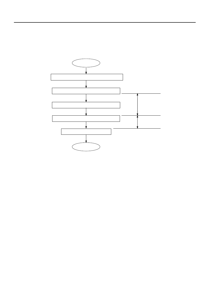
Insert the master key in the key cylinder.
Driver’s door: Open
→
Close 7 times
Ignition switch: LOCK
→
ON 6 times
Remove the master key.
START
END
*1
*2
within
15 secs.
within
20 secs.
All doors closed. No key in the key cylinder.
–
BODY ELECTRICAL
ENGINE IMMOBILISER SYSTEM
BE–141
3545
3.
ERASURE OF TRANSPONDER KEY CODE
Do this operation to erase transponder key registration from the transponder key computer.
HINT:
Delete all other master and sub–key codes leaving the master key code to use the operation. When using
the key which was used before deletion, it is necessary to register the code again.
*1: Insert the master cylinder into the key cylinder.
Turn the ignition switch to LOCK
→
ON 6 times within 15 seconds.
*2: Open and close driver’s door 7 times and remove the master key within 20 seconds after completion of
the previous operation.
HINT:
When any operation time described above is over, registration mode completes.
When the next procedure is performed while the timer is working, the timer completes counting time,
then the next timer starts.
4.
ECU COMMUNICATION ID REGISTRATION
NOTICE:
The ECU communication ID should be registered when the transponder key ECU and/or the
ECM is replaced, in order to match these ECM COMMUNICATION ID.
The engine cannot be started unless the ECM COMMUNICATION ID matches.
(a)
Register the ECU communication ID.
(1)
After the transponder key ECU and/or the ECM is replaced, turn the ignition switch ON (the en-
gine is not running).
(2)
Short the Tc and CG terminals of the DLC3 and leave it as it is for 30 minutes.
(3)
Check that the engine starts.
BE0D8–11
I28395
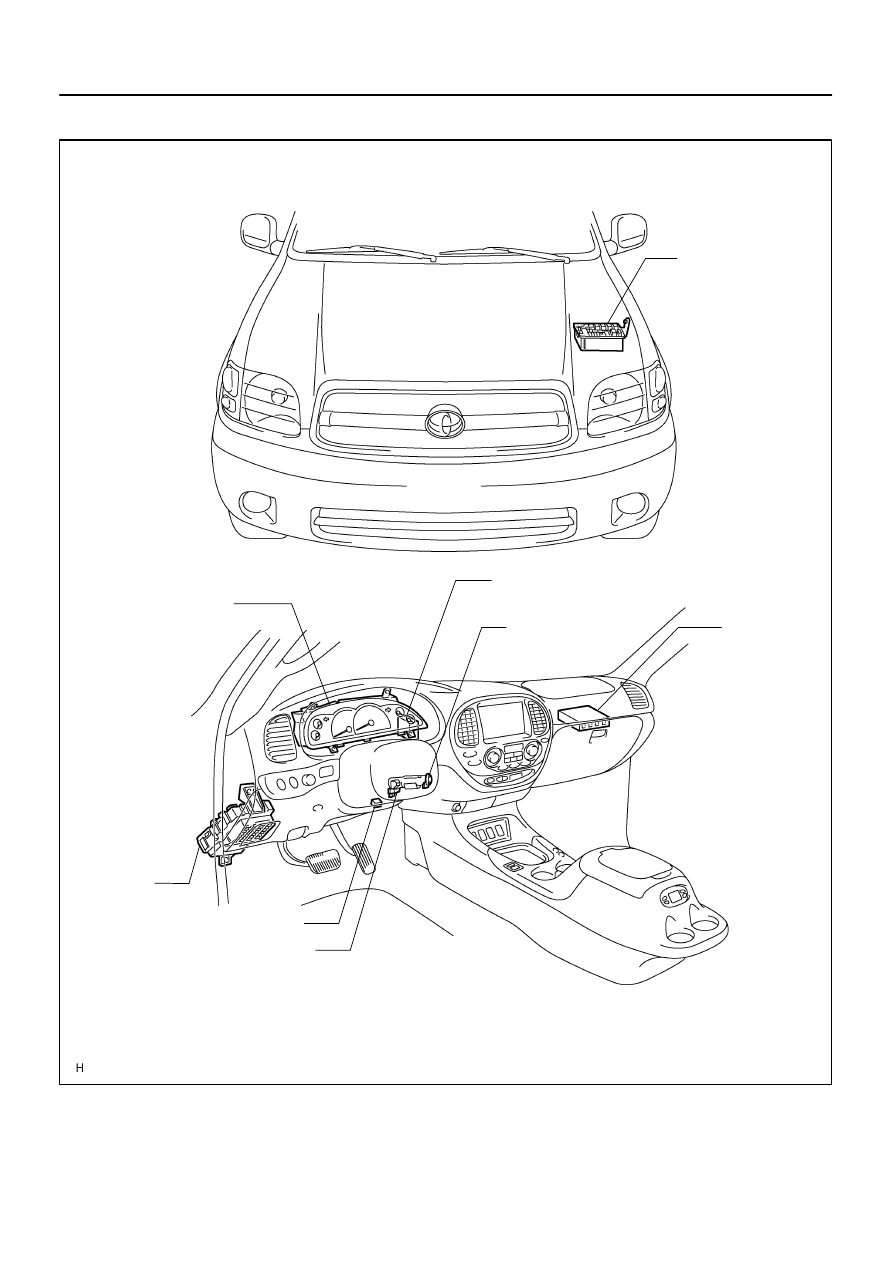
Transponder Key Coil
Transponder Key Amplifier
ECM
Instrument
Panel J/B
IGN 1 Fuse
Engine Room J/B
ECU–B Fuse
EFI No. 1 Fuse
Combination Meter
Security Indicator Light
DLC3
Transponder Key ECU
(Located behind the combination meter)
BE–142
–
BODY ELECTRICAL
ENGINE IMMOBILISER SYSTEM
3546
LOCATION
BE2D6–02
I10154
I24870
12
6
–
BODY ELECTRICAL
ENGINE IMMOBILISER SYSTEM
BE–143
3547
INSPECTION
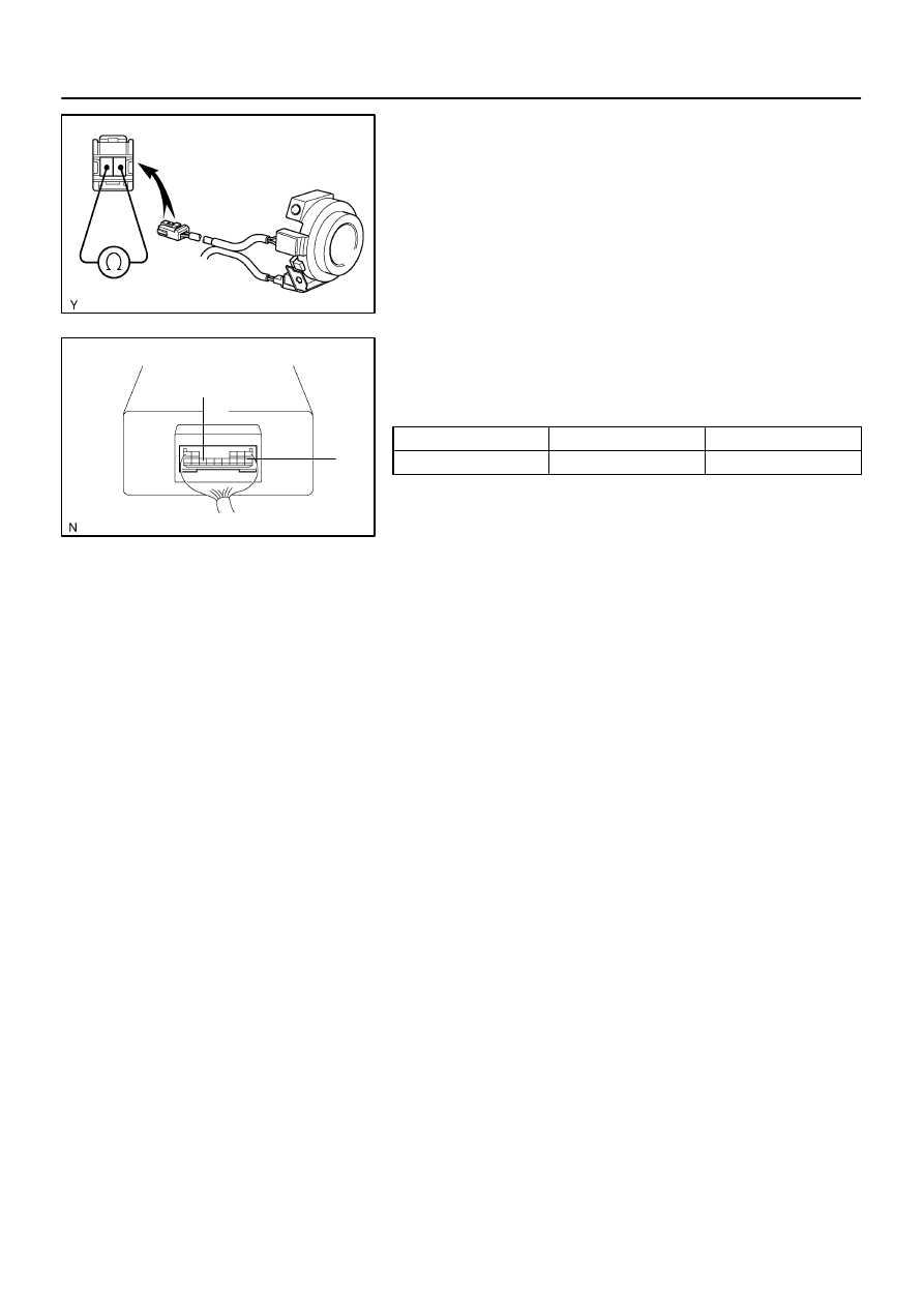
1.
INSPECTION TRANSPONDER KEY COIL CONTINU-
ITY
Check that there is continuity between terminals 1 and 2.
If continuity is not as specified, replace the coil.
2.
INSPECT TRANSPONDER KEY ECU CIRCUIT
Connect the wire harness side connector to the ECU and in-
spect the wire harness side connector from the back side, as
shown in the table below.
Condition
Tester connection
Specified condition
Always
6 – 12
Battery positive voltage
If the circuit is as specified, replace the ECU with a new one.
If the circuit is not as specified, inspect the circuit connected to
other parts.
BE0FY–32
I28423
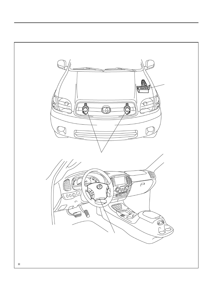
Horn
Horn Switch
Engine Room J/B
HORN Relay
HORN Fuse
BE–144
–
BODY ELECTRICAL
HORN SYSTEM
3548
HORN SYSTEM
LOCATION
Нет комментариевНе стесняйтесь поделиться с нами вашим ценным мнением.
Текст