Toyota Sequoia (2005). Manual — part 211

–
DIAGNOSTICS
AUTOMATIC TRANSMISSION
DI–639
833
2
Perform active test
HINT:
Performing the ACTIVE TEST using the hand–held tester allows the relay, VSV, actuator and so on to oper-
ate without parts removal. Performing the ACTIVE TEST as the first step of troubleshooting is one method
to shorten labor time.
It is possible to display the DATA LIST during the ACTIVE TEST.
(a)
Warm up the engine.
(b)
Turn the ignition switch off.
(c)
Connect the hand–held tester to the DLC3.
(d)
Turn the ignition switch to the ON position.
(e)
Turn on the tester.
(f)
Select the item ”DIAGNOSIS / ENHANCED OBD II / ACTIVE TEST”.
(g)
According to the display on the tester, perform the ”ACTIVE TEST”.
HINT:
While driving, the shift position can be forcibly changed with the hand–held tester.
Comparing the shift position commanded by the ACTIVE TEST with the actual shift position enables you
to confirm the problem (See page
).
Standard:
Item
Test Details
Diagnostic Note
SHIFT
[Test Details]
Operate the shift solenoid valve and set each shift position by yourself.
[Vehicle Condition]
Less than 50 km/h (31 mph)
[Others]
Press ”
→
” button: Shift up
Press ”
←
” button: Shift down
Possible to check the operation of
the shift solenoid valves.
HINT:
This test can be conducted when the vehicle speed is 50 km/h (31 mph) or less.
The 4th to 5th up–shiftings must be performed with the accelerator pedal released.
The 5th to 4th down–shiftings must be performed with the accelerator pedal released.
Do not operate the accelerator pedal for at least 2 seconds after shifting and do not shift successively.
The shift position commanded by the ECM is shown in the DATA LIST (SHIFT) display on the hand–
held tester.
OK:
Gear position changes in accordance with the tester command.
NG
Repair or replace valve body
OK

DI–640
–
DIAGNOSTICS
AUTOMATIC TRANSMISSION
834
3
Clear the DTC and running test.
CHECK:
Clear the DTC, and check DTC again after conducting the ”MONITOR DRIVE PATTERN FOR ECT TEST”
(See page
OK:
No DTC code
NG
Repair or replace valve body
OK
END

–
DIAGNOSTICS
AUTOMATIC TRANSMISSION
DI–641
835
DTC
P0973
Shift Solenoid ”A” Control Circuit Low
(Shift Solenoid Valve S1)
DTC
P0974
Shift Solenoid ”A” Control Circuit High
(Shift Solenoid Valve S1)
CIRCUIT DESCRIPTION
Shifting from 1st to 5th is performed in combination with ”ON” and ”OFF” operation of the shift solenoid valves
SL1, SL2, S1, S2 and SR which are controlled by the ECM. If an open or short circuit occurs in either of the
shift solenoid valves, the ECM controls the remaining normal shift solenoid valves to allow the vehicle to be
operated smoothly (See page
).
DTC No.
DTC Detection Condition
Trouble Area
P0973
ECM detects short in solenoid valve S1 circuit 2 times when
solenoid valve S1 is operated (1–trip detection logic)
Short in shift solenoid valve S1 circuit
Shift solenoid valve S1
ECM
P0974
ECM detects open in solenoid valve S1 circuit 2 times when
solenoid valve S1 is not operated (1–trip detection logic)
Open in shift solenoid valve S1 circuit
Shift solenoid valve S1
ECM
MONITOR DESCRIPTION
These DTCs indicate an open or short in the shift solenoid valve S1 circuit. When there is an open or short
circuit in any shift solenoid valve circuit, the ECM detects the problem and illuminates the MIL and stores
the DTC. When the shift solenoid valve S1 is on, if resistance is 8
Ω
or less, the ECM determines there is
a short in the shift solenoid valve S1 circuit.
When the shift solenoid valve S1 is off, if resistance is 100 k
Ω
or more, the ECM determines there is an open
in the shift solenoid valve S1 circuit (See page
MONITOR STRATEGY
R l t d DTC
P0973
Shift solenoid valve S1/Range check (Low resistance)
Related DTCs
P0974
Shift solenoid valve S1/Range check (High resistance)
Required sensors/Components
Shift solenoid valve S1
Frequency of operation
Continuous
Duration
0.064 sec.
MIL operation
Immediate
Sequence of operation
None
DIDJI–01
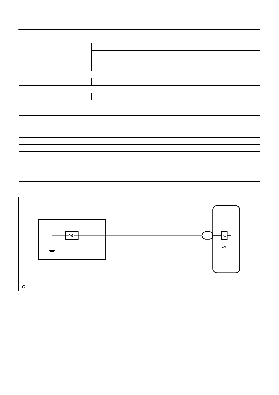
D14170
E1
Electronically Controlled
Transmission Solenoid
ECM
11
E7
S1
8
W
R
S1
+B
CPU
DI–642
–
DIAGNOSTICS
AUTOMATIC TRANSMISSION
836
TYPICAL ENABLING CONDITIONS
It
Specification
Item
Minimum
Maximum
The monitor will run whenever these
DTCs are not present.
See page
Range check (Low resistance)
Shift solenoid valve S1
ON
Range check (High resistance)
Shift solenoid valve S1
OFF
TYPICAL MALFUNCTION THRESHOLDS
Detection criteria
Threshold
Range check (Low resistance)
Shift solenoid valve S1 resistance
8
Ω
or less
Range check (High resistance)
Shift solenoid valve S1 resistance
100 k
Ω
or more
COMPONENT OPERATING RANGE
Parameter
Standard value
Shift solenoid valve S1
Resistance: 11 to 15
Ω
at 20
°
C (68
°
F)
WIRING DIAGRAM
Нет комментариевНе стесняйтесь поделиться с нами вашим ценным мнением.
Текст