Toyota Sequoia (2005). Manual — part 234
DIDDK–01
F19441
SHB
H15
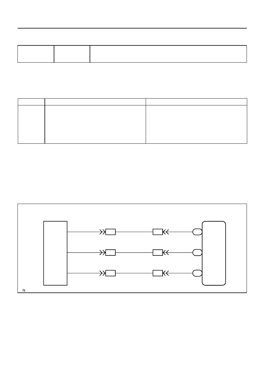
Height Control Sensor Sub–assy
1
G–O
Suspension Control ECU
SBL
BM1
G–O
5
IN1
18
G–O
S25
15
SHRL
2
GR–L
BM1
6
IN1
17
S25
17
GR–L
GR–L
SHRL
SHG
3
L–R
BM1
7
L–R
L–R
IN1
16
S25
19
SGL
–
DIAGNOSTICS
AIR SUSPENSION SYSTEM
DI–731
925
CIRCUIT INSPECTION
DTC
C1714/14 Left Rear Height Control Sensor Circuit
CIRCUIT DESCRIPTION
A magnetic circuit installed on the shaft inside the height control sensor rotates around the linear IC. The
linear IC outputs voltage corresponding to the level of magnetic strength generated by the magnetic circuit.
As a result, voltage corresponding to the shaft rotation angle is supplied to the suspension control ECU.
DTC No.
DTC Detecting Condition
Trouble Area
C1714/14
Either of the following conditions is detected:
1. With the ignition switch ON, a voltage of the height control
sensor sub–assy is 4.7 V or more or 0.3 V or less for 1 sec.
or more.
2. With the ignition switch ON, a voltage of the height control
sensor sub–assy is 5.5 V or more or 4.3 V or less for 0.5
sec. or more.
Height control sensor sub–assy
Height control sensor circuit
Suspension control ECU
HINT:
Once the ECU stores DTC C1714/14 in the memory, vehicle height control is suspended until a normal
signal is input to the ECU from the height control sensor sub–assy. However, control resumes if the
ignition switch is turned OFF, and then turned ON again.
When the suspension control ECU detects a malfunction in the height control sensor, the height control
indicator lamp ”N” comes on or blinks, and control of the height control sensor ”UP” and ”DOWN” opera-
tion is halted.
WIRING DIAGRAM
DI–732
–
DIAGNOSTICS
AIR SUSPENSION SYSTEM
926
INSPECTION PROCEDURE
HINT:
Proceed to troubleshooting following the flow chart, regardless of whether or not DTC C1714/14 is dis-
played.
If DTC C1761/61 (ECU malfunction) and/or C1774/74 (power source circuit) is displayed, perform the
inspection necessary for DTC C1761/61 (See page
first.
(If DTC C1761/61 and C1774/74 are output at the same time, perform the inspection necessary for
DTC C1774/74 first.)
Start the inspection from step 1 when using the hand–held tester, and start from step 2 when not using
the hand–held tester.
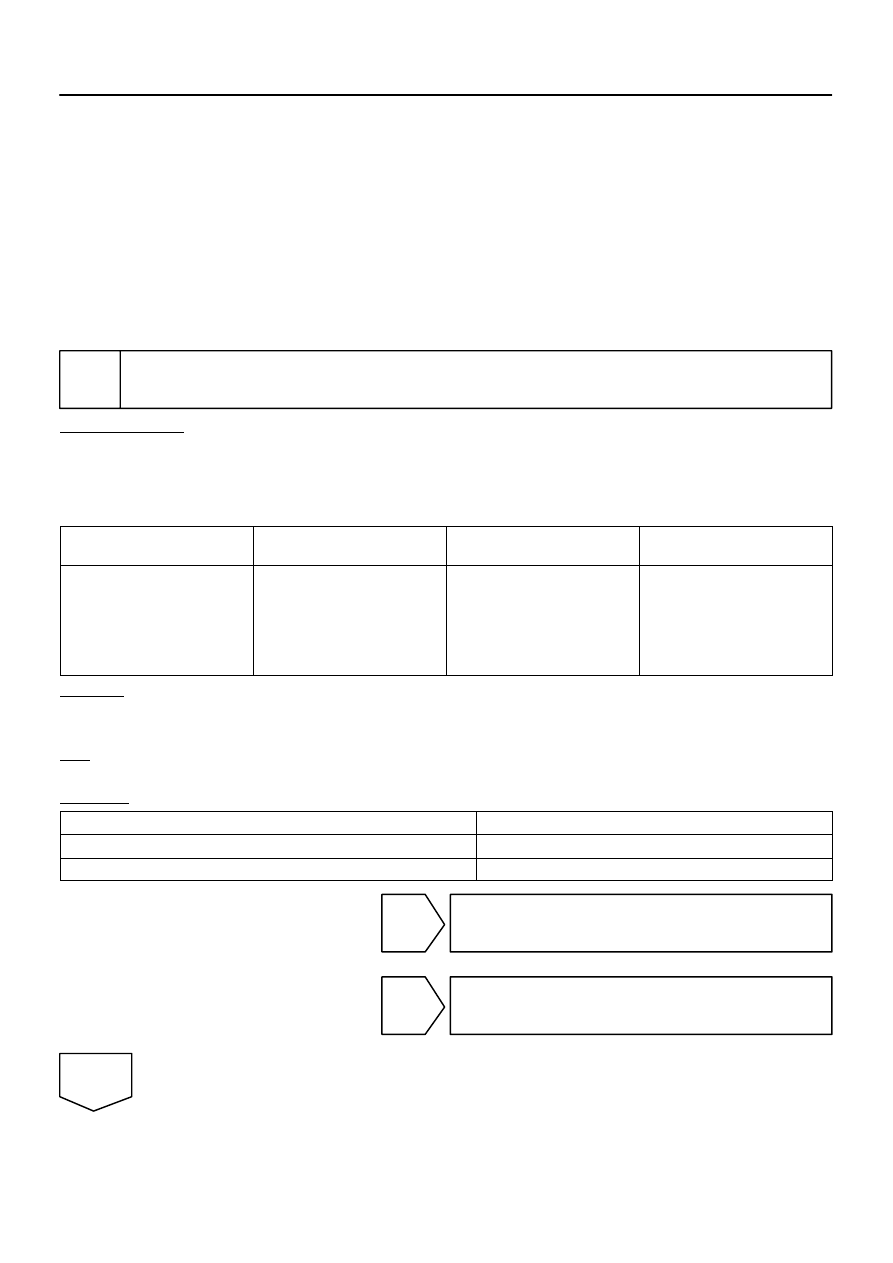
1
Read value of the hand–held tester.
PREPARATION:
(a)
Connect the hand–held tester to the DLC3.
(b)
Turn the ignition switch to the ON position, and push the hand–held tester main switch ON.
(c)
Select the item ”RL HEIGHT” in the DATA LIST, and read its value displayed on the hand–held tester.
AIR SUSPENSION:
Item
Measurement Item / Range (Dis-
play)
Normal Condition
Diagnostic Note
RL HEIGHT
Left rear height control sensor
reading / min.: –3276.7 mm
(–129.004 in.), max.: 3276.8 mm
(129.008 in.)
2WD:
Min.: –15 mm (–0.59 in.)
Max.: 40 mm (1.57 in.)
4WD:
Min.: –30 mm (–1.18 in.)
Max.: 40 mm (1.57 in.)
–
CHECK:
Check the vehicle height value of the height control sensor sub–assy with the hand–held tester while press-
ing the height control switch ”UP” or ”DOWN”.
OK:
Vehicle height value changes.
RESULT:
NG
A
OK (When troubleshooting according to the PROBLEM SYMPTOMS TABLE)
B
OK (When troubleshooting according to the DTC chart)
C
B
Proceed to next circuit inspection shown in
problem symptoms table (See page
C
Replace suspension control ECU
(See page
).
A
F19456
Wire Harness Connector
Front View:
H15
SHB
SHG
F16805
S25
Suspension Control ECU
Wire Harness View:
SGL
SBL
F19456
Height Control Sensor Sub–assy
Connector Front View:
SHG
H15
SHB
–
DIAGNOSTICS
AIR SUSPENSION SYSTEM
DI–733
927
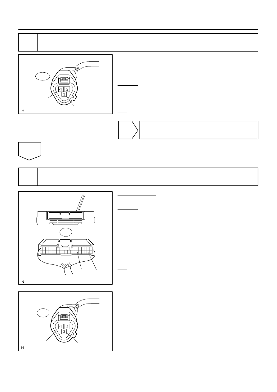
2
Check harness and connector (Height control sensor sub–assy power source).
PREPARATION:
(a)
Disconnect the height control sensor sub–assy connec-
tor.
(b)
Turn the ignition switch ON.
CHECK:
Measure the voltage between terminals 1 (SHB) and 3 (SHG)
of the height control sensor sub–assy wire harness side con-
nector.
OK:
Voltage: 4.5 to 5.5 V
OK
NG
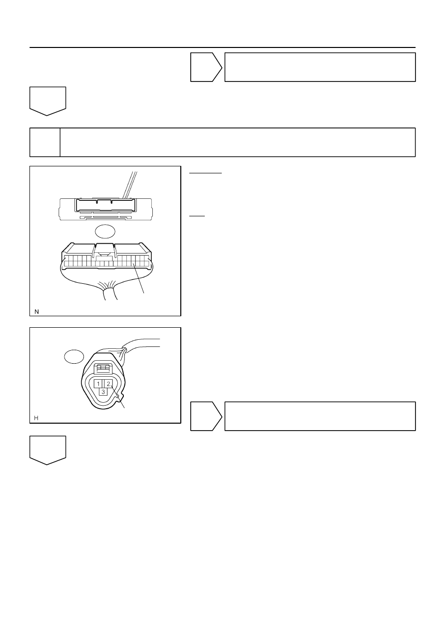
3
Check harness and connector (Height control sensor sub–assy – Suspension
control ECU).
PREPARATION:
Disconnect the ECU connector.
CHECK:
(a)
Check for an open or short circuit in the harness and the
connector between terminal 1 (SHB) of the height control
sensor sub–assy and S25–15 (SBL) of the suspension
control ECU.
(b)
Check for an open or short circuit in the harness and the
connector between terminal 3 (SHG) of the height control
sensor sub–assy and S25–19 (SGL) of the suspension
control ECU.
OK:
There is no open or short circuit in the wire harness.
F16805
S25
Suspension Control ECU
Wire Harness View:
SHRL
F19456
Height Control Sensor Sub–assy
Connector Front View:
H15
SHRL
DI–734
–
DIAGNOSTICS
AIR SUSPENSION SYSTEM
928
NG
Repair or replace harness or connector.
OK
4
Check harness and connector (Height control sensor sub–assy – Suspension
control ECU.
CHECK:
Check for an open or short circuit in the harness and the con-
nector between terminal 2 (SHRL) of the height control sensor
sub–assy and S25–17 (SHRL) of the suspension control ECU.
OK:
There is no open or short in the wire harness.
NG
Repair or replace harness or connector.
OK
Нет комментариевНе стесняйтесь поделиться с нами вашим ценным мнением.
Текст