Toyota Sequoia (2005). Manual — part 906
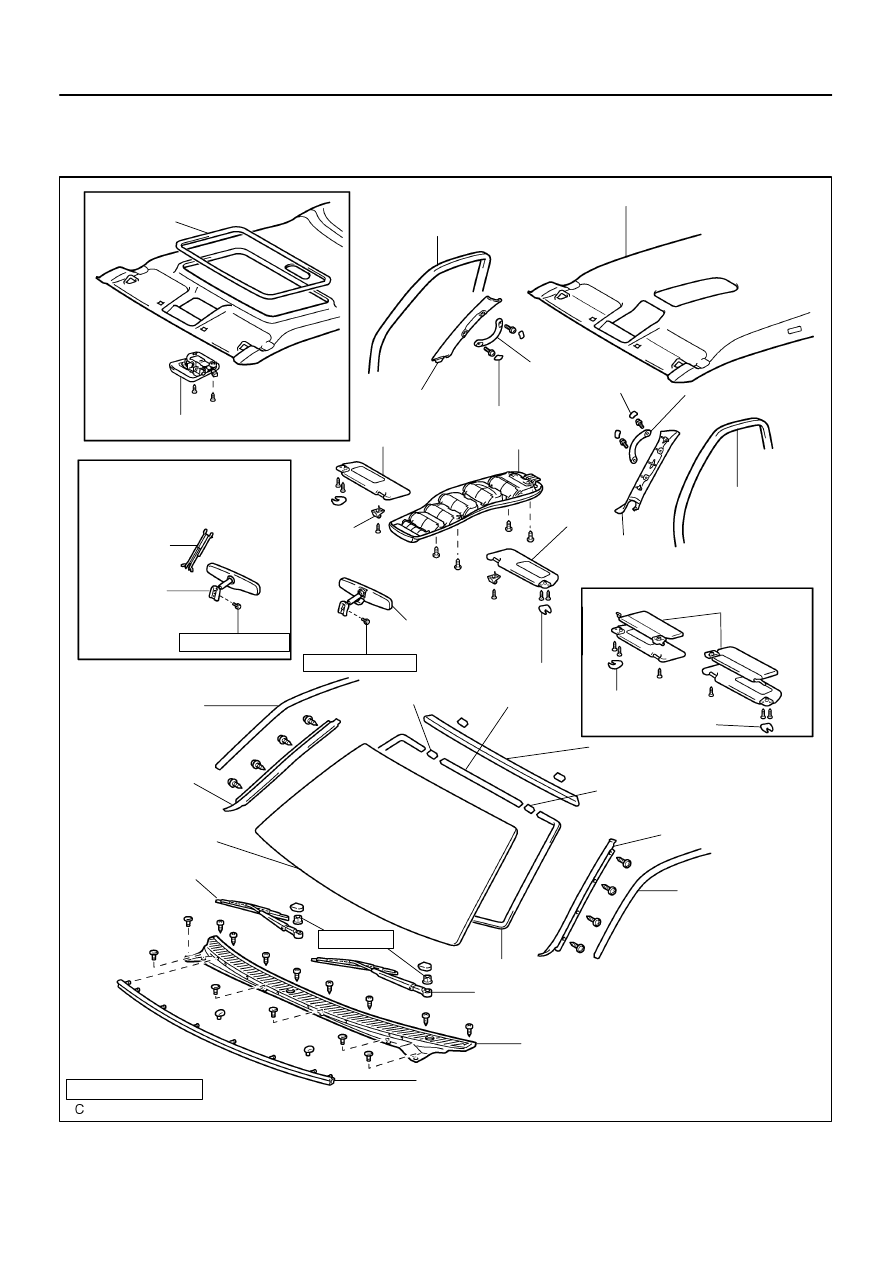
BO46I–02
H18890
Roof Console Box
Front Door Opening
Trim Weatherstrip
Roof Headlining
Assist Grip
Assist Grip Plug
Front Pillar Garnish
Sun Visor
Roof Console Box
Assist Grip
Front Pillar
Garnish
Sun Visor
Holder
Holder
Inner Rear
View Mirror
No. 2 Stopper
Windshield Outside
Upper Moulding
Windshield Outside Moulding
Roof Side Rail
Weatherstrip
Windshield
Outside Moulding
Windshield Glass
Wiper Arm
Wiper Arm
Cowl Top Ventilator Louver
Hood to Cowl Top Seal
Non–reusable part
N·m (kgf·cm, ft·lbf) : Specified torque
No. 2 Stopper
Dam
w/ Sliding roof:
Roof Side Rail
Weatherstrip
w/ Electro chrmic
inner rear view mirror:
Mirror Cover
Inner Rear
View Mirror
2.5
(25, 22 in.·lbf)
Front Door
Opening Trim
Weatherstrip
w/
Double sun visor:
Sun Visor
2.5 (25, 22 in.·lbf)
Dam
Assist Grip Plug
Holder
Holder
Siding Roof
Headlining
Trim
20 (204, 15)
BO–60
–
BODY
WINDSHIELD
3613
WINDSHIELD
COMPONENTS
BO4HJ–01
H16717
Clip
H16734
2 Clips
H16735
4 Clips
H18891
–
BODY
WINDSHIELD
BO–61
3614
REMOVAL
1.
REMOVE FRONT DOOR OPENING TRIM WEATH-
ERSTRIPS
2.
REMOVE FRONT PILLAR GARNISH
(a)
Remove the assist grip.
(1)
Using a screwdriver, remove the 2 assist grip plugs.
HINT:
Tape the screwdriver tip before use.
(2)
Remove the 2 screws and assist grip.
(b)
Remove the front pillar garnish.
(c)
Use the same manner described above to the other side.
3.
REMOVE SUN VISORS AND HOLDERS
4.
w/ Sliding roof:
REMOVE ROOF CONSOLE BOX
(a)
Remove the 2 screws.
(b)
Using a screwdriver, remove the roof console box.
HINT:
Tape the screwdriver tip before use.
(c)
Disconnect the connectors.
5.
w/o Sliding roof:
REMOVE ROOF CONSOLE BOX
(a)
Remove the 4 screws.
(b)
Using a screwdriver, remove the roof console box.
HINT:
Tape the screwdriver tip before use.
(c)
Disconnect the connectors.
6.
w/o Electro chromic inner rear view mirror:
REMOVE INNER REAR VIEW MIRROR
Remove the torx screw and inner rear view mirror as shown in
the illustration.
H18892
H16708
H05613
BO5232
H05619
BO–62
–
BODY
WINDSHIELD
3615
7.
w/ Electro chromic inner rear view mirror:
REMOVE INNER REAR VIEW MIRROR
(a)
Remove the mirror cover.
(b)
Disconnect the connector.
(c)
Remove the torx screw and inner rear view mirror.
8.
REMOVE WIPER ARMS
(a)
Using a screwdriver, remove the 2 caps.
HINT:
Tape the screwdriver tip before use.
(b)
Remove the 2 nuts and wiper arms.
9.
REMOVE COWL TOP VENTILATOR LOUVER
(a)
Remove the hood to cowl top seal.
(b)
Using a clip remover, remove the 6 clips.
(c)
Remove the 8 screws and cowl top ventilator louver.
10.
REMOVE ROOF SIDE RAIL WEATHERSTRIP
Using SST, pull off the roof side rail weatherstrip from front end.
SST
09806–30010
11.
REMOVE WINDSHIELD OUTSIDE MOULDINGS
Remove the 8 screws and windshield outside mouldings.
12.
REMOVE WINDSHIELD OUTSIDE UPPER MOULDING
Using a knife, cut off the moulding as shown in the illustration.
NOTICE:
Do not damage the body with the knife.
13.
REMOVE WINDSHIELD GLASS
(a)
Push piano wire through between the body and glass
from the interior.
(b)
Tie both wire ends to wooden blocks or similar objects.
HINT:
Apply protective tape to the outer surface to keep the surface
from being scratched.
NOTICE:
When separating the glass, be careful not to damage the
paint and exterior ornaments. To prevent scratching the
safety pad when removing the windshield, place a plastic
sheet between the piano wire and the safety pad.
(c)
Cut the adhesive by pulling the piano wire around it.
(d)
Remove the glass.
NOTICE:
Leave as much of the adhesive on the body as possible
when cutting off the glass.
BO4HK–01
BO4420
Adhesive
BO5231
H12587
H12588
Stopper
A
–
BODY
WINDSHIELD
BO–63
3616
INSTALLATION
1.
CLEAN AND SHARE CONTACT SURFACE OF BODY
(a)
Using a knife, cut away any rough areas on the body.
HINT:
Leave the adhesive on the body as much as possible.
(b)
Clean the cut surface of the adhesive with a shop rag sat-
urated in cleaner.
HINT:
Even if the adhesive has been removed, clean the body.
2.
CLEAN REMOVE GLASS
(a)
Remove the damaged No. 2 stoppers and dams.
(b)
Using a scraper, remove the adhesive sticking to the
glass.
(c)
Clean the glass with cleaner.
NOTICE:
Be careful not to damage the glass.
Do not touch the glass face after cleaning it.
3.
w/ No. 1 stopper:
REPLACE NO. 1 STOPPERS
(a)
Remove the damaged stoppers.
(b)
Cut off the old adhesive around the stopper installation
area.
NOTICE:
Be careful not to damage the body.
(c)
Clean the installation area.
(d)
Attach new stoppers to the body so that the notches on
the body will align with the stoppers as shown in the il-
lustration.
HINT:
Make sure that the stoppers are installed facing the correct
direction.
4.
INSTALL NEW NO. 2 STOPPERS
Attach new stoppers to the glass so that the ceramic notches
on the glass will align with the stoppers as shown in the illustra-
tion.
HINT:
Make sure that the stoppers are installed facing the correct
direction.
A:
w/ No. 1 stopper: 8.0 mm (0.315 in.)
w/o No. 1 stopper: 8.9 mm (0.350 in.)
Нет комментариевНе стесняйтесь поделиться с нами вашим ценным мнением.
Текст