Toyota Sequoia (2005). Manual — part 222
D14166
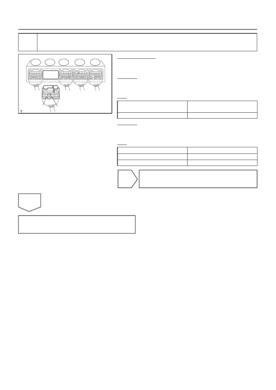
ECM:
SLU+
SLU–
E8
E7
E6
E5
E4
–
DIAGNOSTICS
AUTOMATIC TRANSMISSION
DI–683
877
2
Check harness and connector (Transmission wire – ECM)
PREPARATION:
(a)
Connect the transmission wire connector.
(b)
Disconnect the ECM connector.
CHECK:
Measure the resistance according to the value(s) in the table
below.
OK:
Tester Connection
Specified Condition
20
C (68
F)
E7 – 15 (SLU+) – E7 – 14 (SLU–)
5.0 to 5.6
Ω
CHECK:
Measure the resistance according to the value(s) in the table
below.
OK:
Tester Connection
Specified Condition
E7 – 15 (SLU+) – Body ground
10 k
Ω
or higher
E7 – 14 (SLU–) – Body ground
↑
NG
Repair or replace the harness or connector
(See page
).
OK
Replace the ECM (See page
D12795
1
2
(–)
(+)
1
2
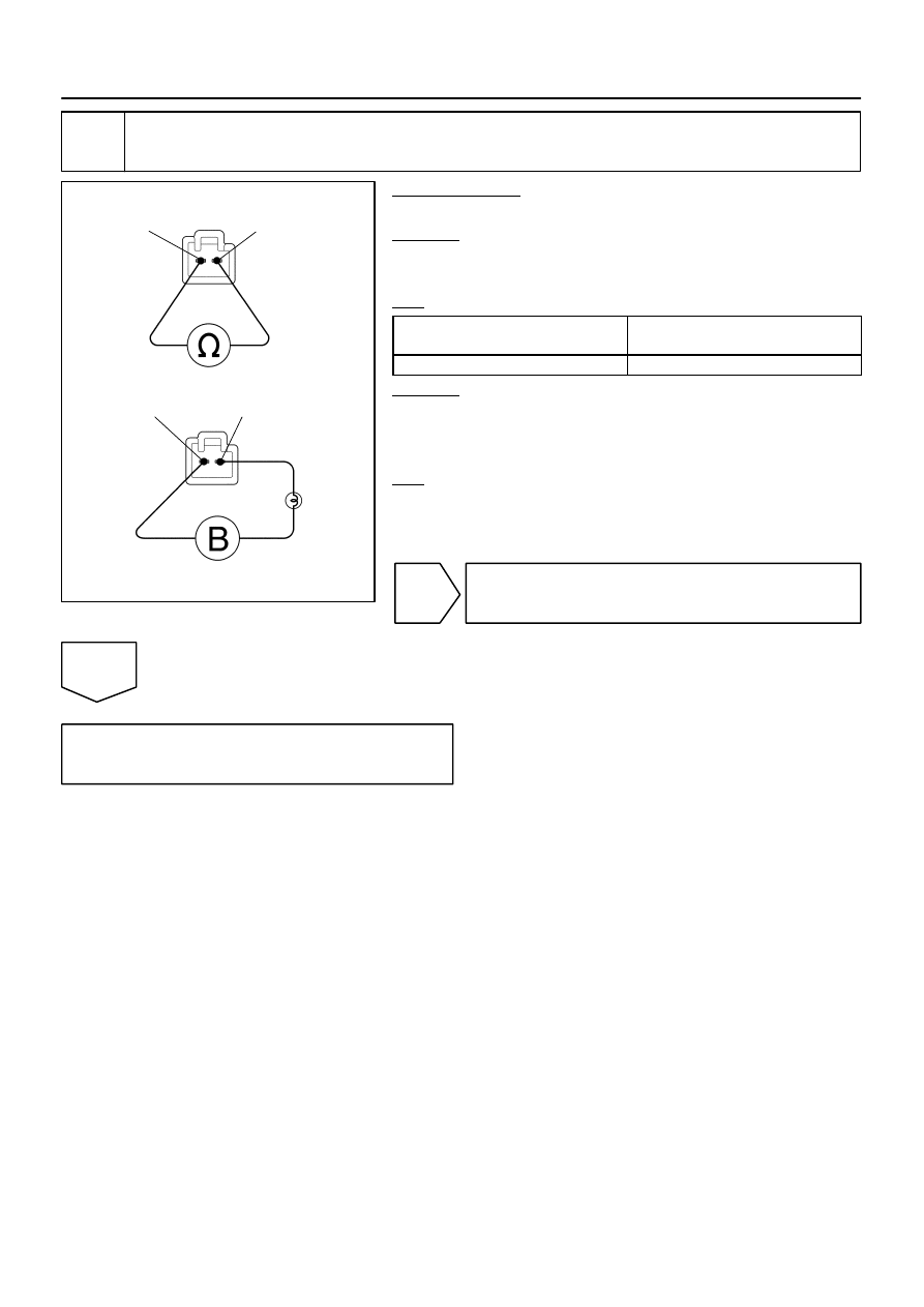
Shift Solenoid Valve SLU:
DI–684
–
DIAGNOSTICS
AUTOMATIC TRANSMISSION
878
3
Inspect shift solenoid valve SLU.
PREPARATION:
Remove the shift solenoid valve SLU (See page
CHECK:
Measure the resistance according to the value(s) in the table
below.
OK:
Tester Connection
Specified Condition
20
C (68
F)
1 – 2
5.0 to 5.6
Ω
CHECK:
Connect the positive (+) lead with a 21 W bulb to terminal 2 and
the negative (–) lead to terminal 1 of the solenoid valve connec-
tor, then check the movement of the valve.
OK:
The solenoid makes an operating sound.
NG
Replace the shift solenoid valve SLU
(See page
OK
Repair or replace the transmission wire
(See page
).

–
DIAGNOSTICS
AUTOMATIC TRANSMISSION
DI–685
879
DTC
P2772
Transfer L4 SW Circuit
CIRCUIT DESCRIPTION
The ECM detects the signal from the transfer L4 position switch.
This DTC indicates that the transfer L4 position switch remains ON.
DTC No.
DTC Detecting Condition
Trouble Area
P2772
Transfer L4 position switch remains ON while vehicle running
under conditions for 18 seconds or more (1–trip detection log-
ic)
(a) Output shaft speed 3000 rpm or less
(b) Transfer shift position is H
Short in transfer L4 position switch circuit
Transfer L4 position switch
4WD control ECU
ECM
MONITOR DESCRIPTION
The ECM monitors the transfer–case L4 position switch to determine when the transfer–case L4 gear is en-
gaged. If the transfer–case L4 gears remain engaged under the following conditions, the ECM will conclude
that there is a malfunction of the L4 position switch:
L4 switch indicated that the L4 transfer–case gears are engaged.
Transfer–case shifter is in the ”H” position.
Transfer–case output shaft rpm is between 750 and 3,000 rpm.
The specified time period has elapsed.
If all of the above conditions are detected, the ECM will conclude that there is a malfunction of the L4 switch,
and illuminate the MIL and store the DTC.
MONITOR STRATEGY
Related DTCs
P2772
Transfer L4 position switch/ON malfunction
Required sensors/Components
Transfer L4 position switch
Frequency of operation
Continuous
D
ti
ON malfunction (A)
1.8 sec.
Duration
ON malfunction (B)
0.5 sec.
MIL operation
1 driving cycle
Sequence of operation
None
TYPICAL ENABLING CONDITIONS
It
Specification
Item
Minimum
Maximum
All:
Output speed sensor circuit
Not circuit malfunction
Vehicle speed sensor circuit
Not circuit malfunction
Transfer neutral position switch
OFF
ON malfunction (A)
Output speed (Transfer output speed)
1,000 to 3,000 rpm
ON malfunction (B)
Output speed (Transfer output speed)
143 rpm or more
–
DIDJQ–01
D14217
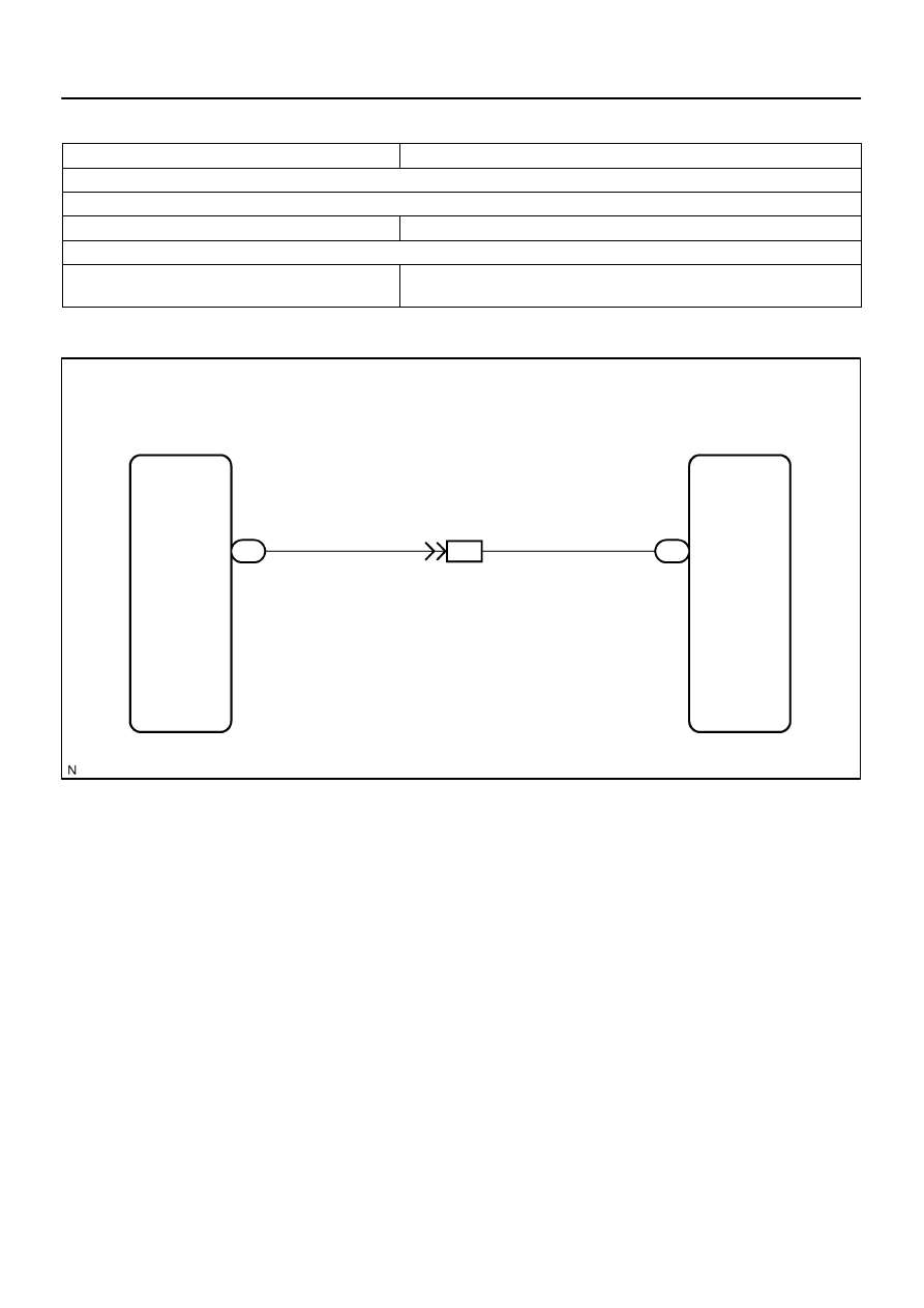
ECM
L4
E6
F23
24
IG4
10
L–R*
L–R*
4WD Control ECU
*: 4WD
L4
13
DI–686
–
DIAGNOSTICS
AUTOMATIC TRANSMISSION
880
TYPICAL MALFUNCTION THRESHOLDS
Detection criteria
Threshold
Both of the following conditions is met: ON malfunctions (A) and (B)
ON malfunction (A)
L4 switch
ON
ON malfunction (B)
Actual Transfer gear ratio
Transfer input speed/Transfer output speed
0.9 to 1.1
WIRING DIAGRAM
Нет комментариевНе стесняйтесь поделиться с нами вашим ценным мнением.
Текст