Toyota Sequoia (2005). Manual — part 409
H01016
H44043
H24013
Airbag
Sensor
Assembly
SFL+
SFL–
Side Squib LH
Floor Wire No. 2
A
B
C
D
S17
–
DIAGNOSTICS
SUPPLEMENTAL RESTRAINT SYSTEM
DI–1431
1625
6
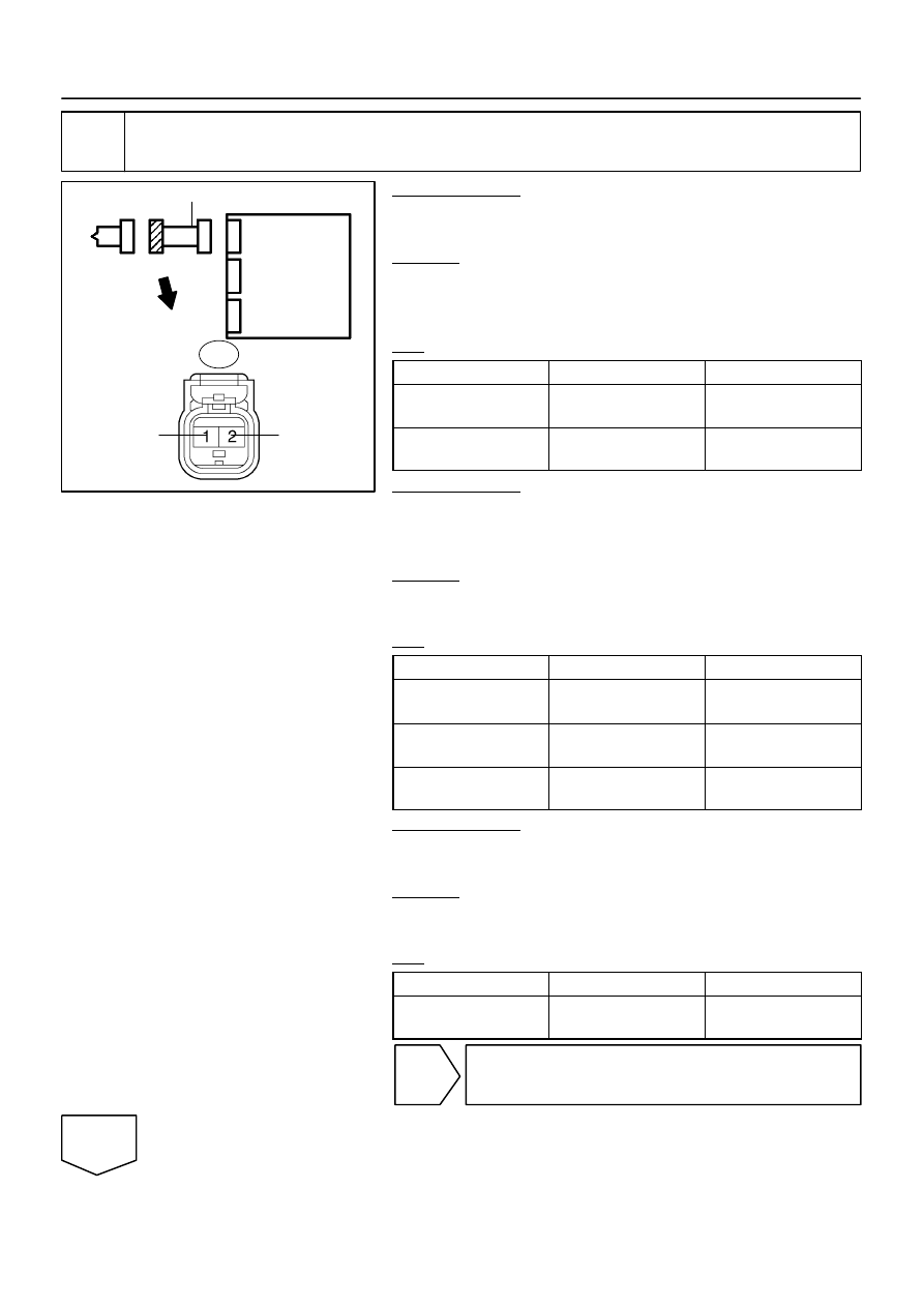
Check floor wire No. 2 (side squib LH circuit).
PREPARATION:
Connect the negative (–) terminal cable to the battery, and wait
for at least 2 seconds.
CHECK:
(a)
Turn the ignition switch to the ON position.
(b)
Measure the voltage according to the value(s) in the table
below.
OK:
Tester Connection
Condition
Specified Condition
S17–1 (SFL+) –
Body ground
Ignition switch ON
Below 1 V
S17–2 (SFL–) –
Body ground
Ignition switch ON
Below 1 V
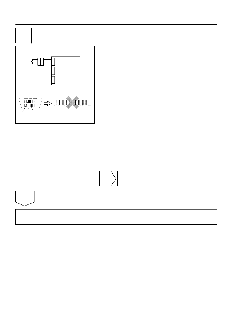
PREPARATION:
(a)
Turn the ignition switch to the LOCK position.
(b)
Disconnect the negative (–) terminal cable from the bat-
tery, and wait for at least 90 seconds.
CHECK:
Measure the resistance according to the value(s) in the table
below.
OK:
Tester Connection
Condition
Specified Condition
S17–1 (SFL+) –
S17–2 (SFL–)
Always
Below 1
Ω
S17–1 (SFL+) –
Body ground
Always
1 M
Ω
or higher
S17–2 (SFL–) –
Body ground
Always
1 M
Ω
or higher
PREPARATION:
Release the activation prevention mechanism built into con-
nector ”B” (see page
CHECK:
Measure the resistance according to the value(s) in the table
below.
OK:
Tester Connection
Condition
Specified Condition
S17–1 (SFL+) –
S17–2 (SFL–)
Always
1 M
Ω
or higher
NG
Repair or replace floor wire No. 2.
OK
H01018
H10600 H16839
H24652
Airbag
Sensor
Assembly
DTC 56
DLC3
TC
CG
Side Squib LH
C
D
DI–1432
–
DIAGNOSTICS
SUPPLEMENTAL RESTRAINT SYSTEM
1626
7
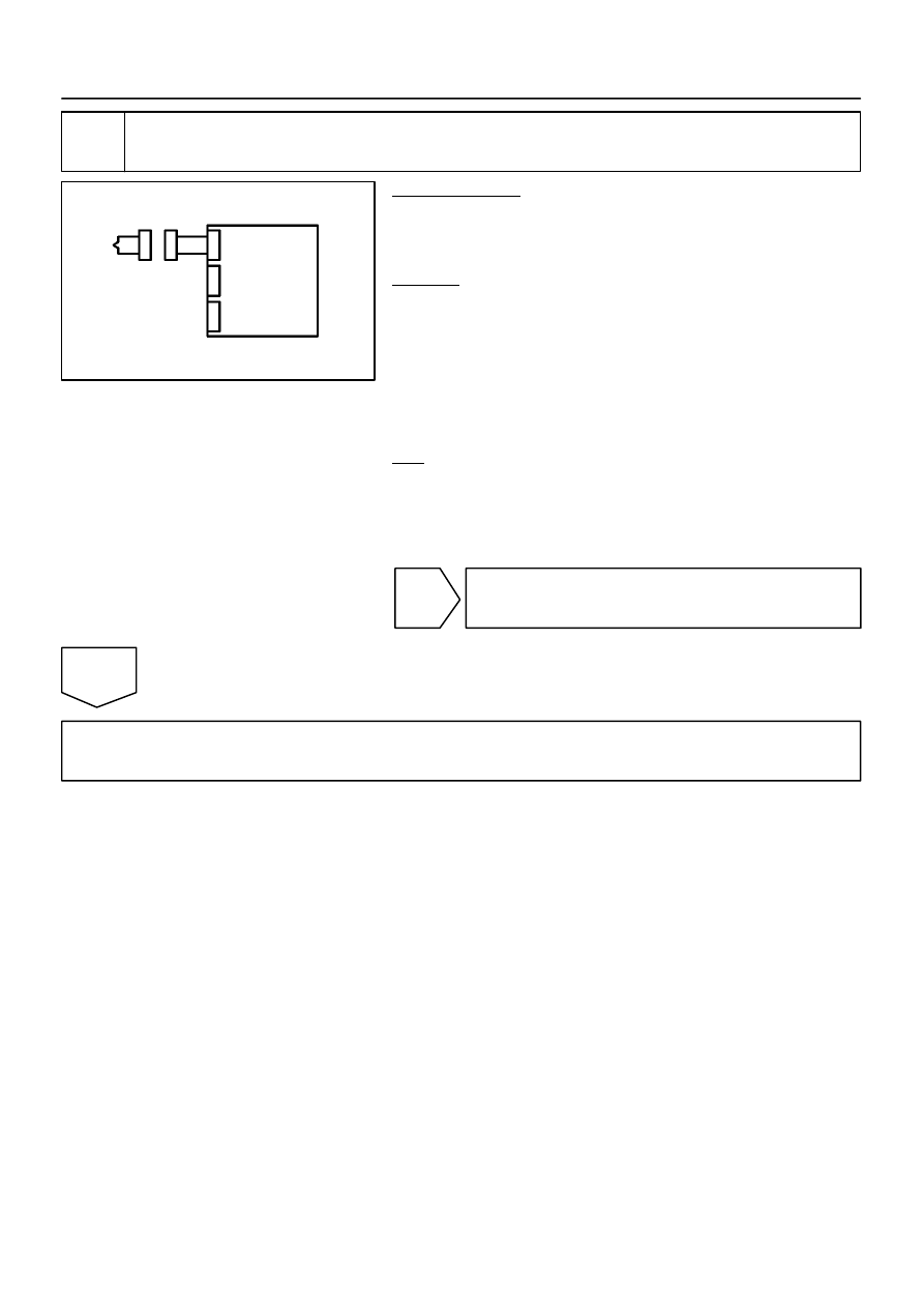
Replace side airbag assembly LH (side squib LH).
PREPARATION:
(a)
Replace the side airbag assembly LH (see page
).
HINT:
Perform the inspection using parts from a normal vehicle if pos-
sible.
(b)
Connect the connectors to the airbag sensor assembly.
(c)
Connect the negative (–) terminal cable to the battery,
and wait for at least 2 seconds.
CHECK:
(a)
Turn the ignition switch to the ON position, and wait for at
least 60 seconds.
(b)
Clear the DTCs stored in memory (see page
(c)
Turn the ignition switch to the LOCK position.
(d)
Turn the ignition switch to the ON position, and wait for at
least 60 seconds.
(e)
OK:
DTC 56 is not output.
HINT:
Codes other than DTC 56 may be output at this time, but they
are not related to this check.
NG
Replace airbag sensor assembly
(see page
).
OK
END
H01017
H23472
Side Squib LH
Airbag
Sensor
Assembly
C
D
–
DIAGNOSTICS
SUPPLEMENTAL RESTRAINT SYSTEM
DI–1433
1627
8
Check airbag sensor assembly.
PREPARATION:
(a)
Connect the connectors to the airbag sensor assembly.
(b)
Connect the negative (–) terminal cable to the battery,
and wait for at least 2 seconds.
CHECK:
(a)
Turn the ignition switch to the ON position, and wait for at
least 60 seconds.
(b)
Clear the DTCs stored in memory (see page
(c)
Turn the ignition switch to the LOCK position.
(d)
Turn the ignition switch to the ON position, and wait for at
least 60 seconds.
(e)
OK:
DTC B1825 is not output.
HINT:
Codes other than DTC B1825 may be output at this time, but
they are not related to this check.
NG
Replace airbag sensor assembly
(see page
).
OK
Go to step 10.
H01017
H44044
H24015
Airbag
Sensor
Assembly
Side Squib
LH
SFL+
SFL–
Floor Wire No. 2
C
D
Service Wire
S17
DI–1434
–
DIAGNOSTICS
SUPPLEMENTAL RESTRAINT SYSTEM
1628
9
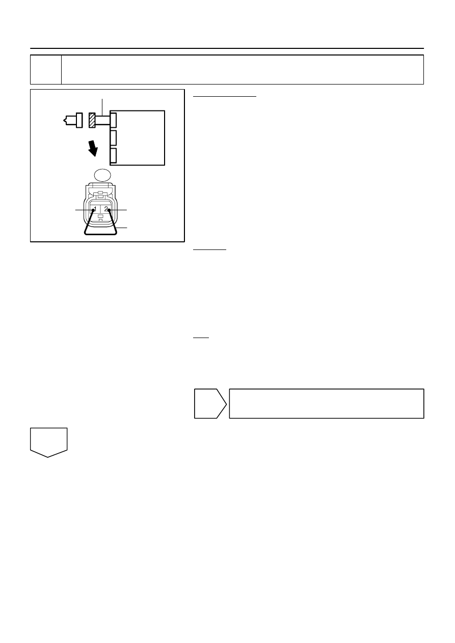
Check airbag sensor assembly.
PREPARATION:
(a)
From the step 5:
Turn the ignition switch to the LOCK position.
(b)
From the step 5:
Disconnect the negative (–) terminal cable from the bat-
tery, and wait for at least 90 seconds.
(c)
Connect the connectors to the airbag sensor assembly.
(d)
Using a service wire, connect S17–1 (SFL+) and S17–2
(SFL–) of the connector ”C”.
NOTICE:
Do not forcibly insert a service wire into the terminals of the
connector when connecting.
(e)
Connect the negative (–) terminal cable to the battery,
and wait for at least 2 seconds.
CHECK:
(a)
Turn the ignition switch to the ON position, and wait for at
least 60 seconds.
(b)
Clear the DTCs stored in memory (see page
(c)
Turn the ignition switch to the LOCK position.
(d)
Turn the ignition switch to the ON position, and wait for at
least 60 seconds.
(e)
OK:
DTC B1826, B1827 or B1828 is not output.
HINT:
Codes other than DTC B1826, B1827 and B1828 may be out-
put at this time, but they are not related to this check.
NG
Replace airbag sensor assembly
(see page
).
OK
Нет комментариевНе стесняйтесь поделиться с нами вашим ценным мнением.
Текст