Toyota Sequoia (2005). Manual — part 325
F19749
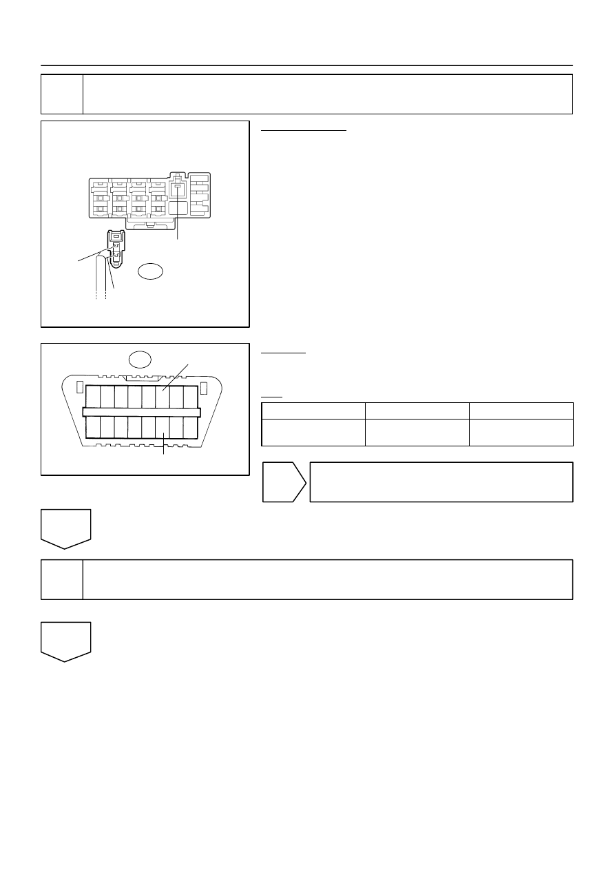
Junction Connector ”A” Side
(w/ Earth Terminal)
Wire Harness View:
J55
W
R
Earth Terminal
1
2
3
4
5
6
7
8
9 10 11 12 13 14 15 16
F19737
DLC3:
D6
CANH
CANL
–
DIAGNOSTICS
CAN COMMUNICATION SYSTEM
DI–1095
1289
5
Check CAN bus lines for short circuit (Translate ECU main bus line).
PREPARATION:
Disconnect the translate ECU main bus line connector (J55)
from the junction connector.
NOTICE:
Before disconnecting the connector, make note of
where it is connected.
Reconnect the connector to its original position.
CHECK:
Measure the resistance according to the value(s) in the table
below.
OK:
Tester connection
Condition
Specified value
D6–6 (CANH) –
D6–14 (CANL)
Ignition Switch OFF
108 to 132
Ω
OK
Go to step 10.
NG
6
Connect the connector.
Reconnect the translate ECU main bus line connector (J55) to the junction connector.
NEXT
F19749
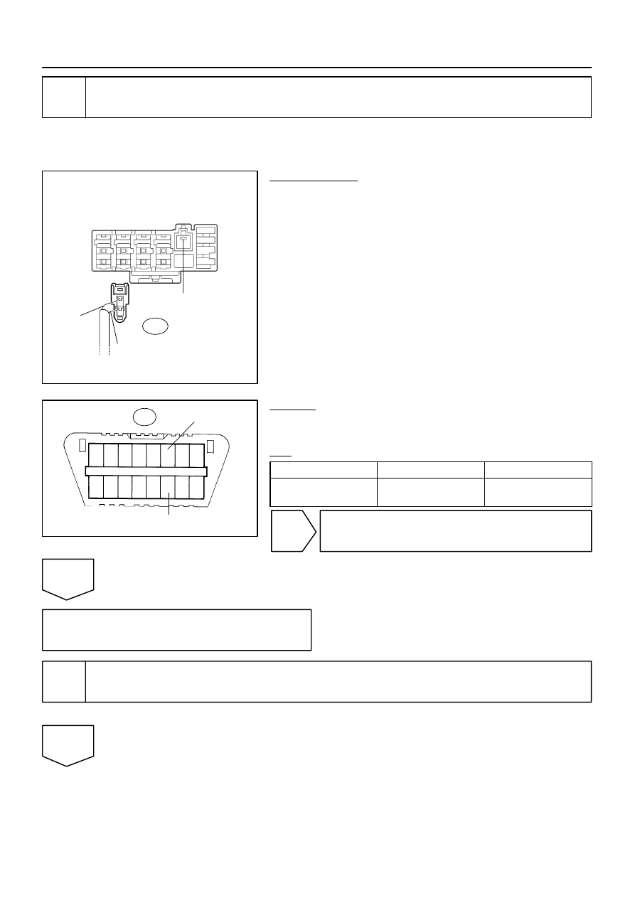
Junction Connector ”A” Side
(w/ Earth Terminal)
Wire Harness View:
J56
W
G
Earth Terminal
1
2
3
4
5
6
7
8
9 10 11 12 13 14 15 16
F19737
DLC3:
D6
CANH
CANL
DI–1096
–
DIAGNOSTICS
CAN COMMUNICATION SYSTEM
1290
7
Check CAN bus lines for short circuit (Suspension control ECU sub bus line).
HINT:
For vehicles without an enhanced air suspension system, go to
NG.
PREPARATION:
Disconnect the suspension control ECU sub bus line connector
(J56) from the junction connector.
NOTICE:
Before disconnecting the connector, make a note of
where it is connected.
Reconnect the connector to its original position.
CHECK:
Measure the resistance according to the value(s) in the table
below.
OK:
Tester connection
Condition
Specified value
D6–6 (CANH) –
D6–14 (CANL)
Ignition Switch OFF
54 to 69
Ω
OK
Go to step 12.
NG
Replace junction connector.
8
Connect the connector.
Reconnect the ECM main bus line connector (J53) to the junction connector.
NEXT
1
2
3
4
5
6
7
8
9 10 11 12 13 14 15 16
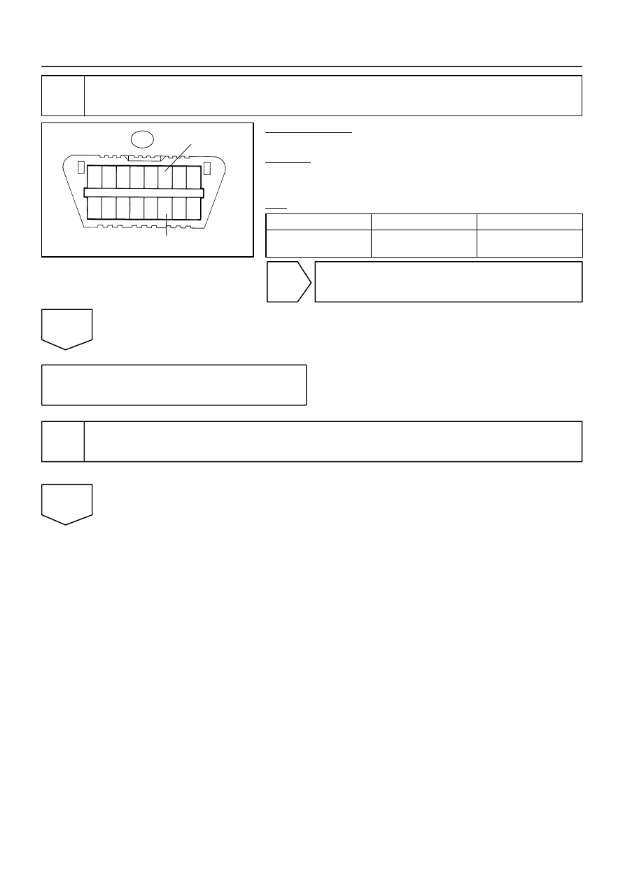
F19737
DLC3:
D6
CANH
CANL
–
DIAGNOSTICS
CAN COMMUNICATION SYSTEM
DI–1097
1291
9
Check CAN bus lines for short circuit (ECM main bus line).
PREPARATION:
Disconnect the ECM connector (E5).
CHECK:
Measure the resistance according to the value(s) in the table
below.
OK:
Tester connection
Condition
Specified value
D6–6 (CANH) –
D6–14 (CANL)
Ignition Switch OFF
108 to 132
Ω
OK
Replace ECM (See page
NG
Repair or replace ECM main bus line or con-
nector (CAN–H, CAN–L).
10
Connect the connector.
Reconnect the translate ECU main bus line connector (J55) to the junction connector.
NEXT

1
2
3
4
5
6
7
8
9 10 11 12 13 14 15 16
F19737
DLC3:
D6
CANH
CANL
DI–1098
–
DIAGNOSTICS
CAN COMMUNICATION SYSTEM
1292
11
Check CAN bus lines for short circuit (Translate ECU main bus line).
PREPARATION:
Disconnect the translate ECU connector (T5).
CHECK:
Measure the resistance according to the value(s) in the table
below.
OK:
Tester connection
Condition
Specified value
D6–6 (CANH) –
D6–14 (CANL)
Ignition Switch OFF
108 to 132
Ω
OK
Replace translate ECU.
NG
Repair or replace translate ECU main bus line
or connector (CAN–H, CAN–L).
12
Connect the connector.
Reconnect the suspension control ECU sub bus line connector (J56) to the junction connector.
NEXT
Нет комментариевНе стесняйтесь поделиться с нами вашим ценным мнением.
Текст