Toyota Sequoia (2005). Manual — part 322
F19706
Suspension
Control ECU
IG
10
S25
B–R
J37
J/C
J37
Sub J/B No.3
B–R
8
3C
8
3A
B–R
Instrument Panel J/B
4
1F
1
1L
ECU–IG
AM1
4
1C
6
1C
B–Y
2
I18
Ignition SW
AM1
IG1
W–L
W
8
ALT
5
B
Battery
F10
FL Block
GND
22
S25
W–B
A
J12
J/C
IF
1
2
1
A
A
Translate ECU
ENG+
ENG–
T5
T5
14
16
ECM
CANH
CANL
Junction Connector
E5
E5
33
34
R
W
W
L
J55
J55
J53
J53
1
2
1
2
J56
J56
1
2
W
G
CANH
CANL
S25
S25
29
28
–
DIAGNOSTICS
CAN COMMUNICATION SYSTEM
DI–1083
1277
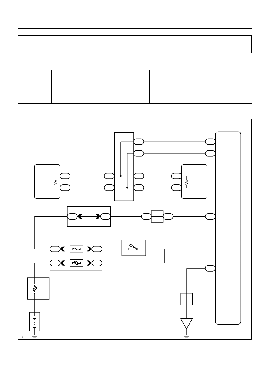
Suspension Control ECU Communication Stop Mode
MODE DESCRIPTION
Detection Item
Symptom
Trouble Area
Suspension Con-
trol ECU Commu-
nication Stop
Mode
”RIAR AIRSUS” is not displayed on the ”BUS CHECK”
screen of the hand–held tester.
DTCs are output from each ECU in suspension control
ECU communication stop mode in the ”DTC COMBINA-
TION TABLE” (see page
Power source or inside the suspension control ECU
Suspension control ECU sub bus line
WIRING DIAGRAM
DIDIB–01
F16805
IG
S25
Suspension Control ECU
Wire Harness View:
GND
DI–1084
–
DIAGNOSTICS
CAN COMMUNICATION SYSTEM
1278
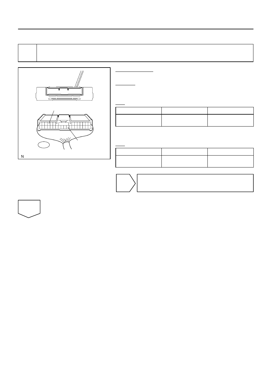
INSPECTION PROCEDURE
1
Check wire harness (Suspension control ECU – Battery and Suspension control
ECU – Body ground).
PREPARATION:
Disconnect the suspension control ECU connector (S25).
CHECK:
(a)
Measure the resistance according to the value(s) in the
table below.
OK:
Tester connection
Condition
Specified value
S25–22 (GND) –
Body ground
Always
Below 1
Ω
(b)
Measure the voltage according to the value(s) in the table
below.
OK:
Tester connection
Condition
Specified value
S25–10 (IG) –
Body ground
Ignition Switch ON
10 to 14 V
NG
Repair or replace harness or connector
(Suspension Control ECU – Battery or Suspen-
sion Control ECU – Body ground).
OK
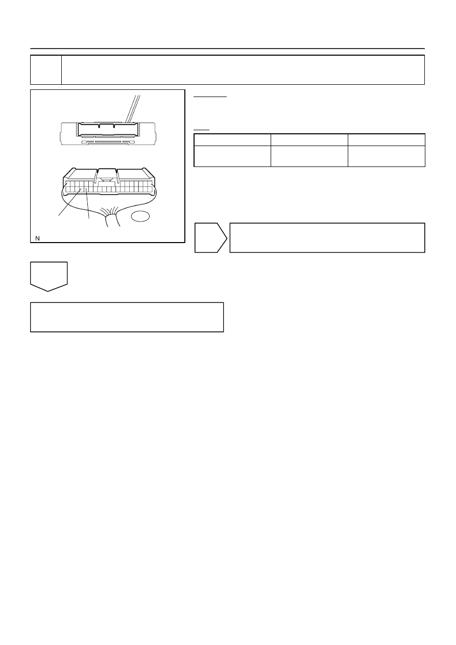
F16805
Suspension Control ECU
Wire Harness View:
CANH
CANL
S25
–
DIAGNOSTICS
CAN COMMUNICATION SYSTEM
DI–1085
1279
2
Check CAN bus line (Suspension control ECU sub bus line).
CHECK:
Measure the resistance according to the value(s) in the table
below.
OK:
Tester connection
Condition
Specified value
S25–29 (CANH) –
S25–28 (CANL)
Ignition Switch OFF
54 to 69
Ω
NG
Repair or replace suspension control ECU sub
bus line or connector (CAN–H, CAN–L).
OK
Replace suspension control ECU
(See page
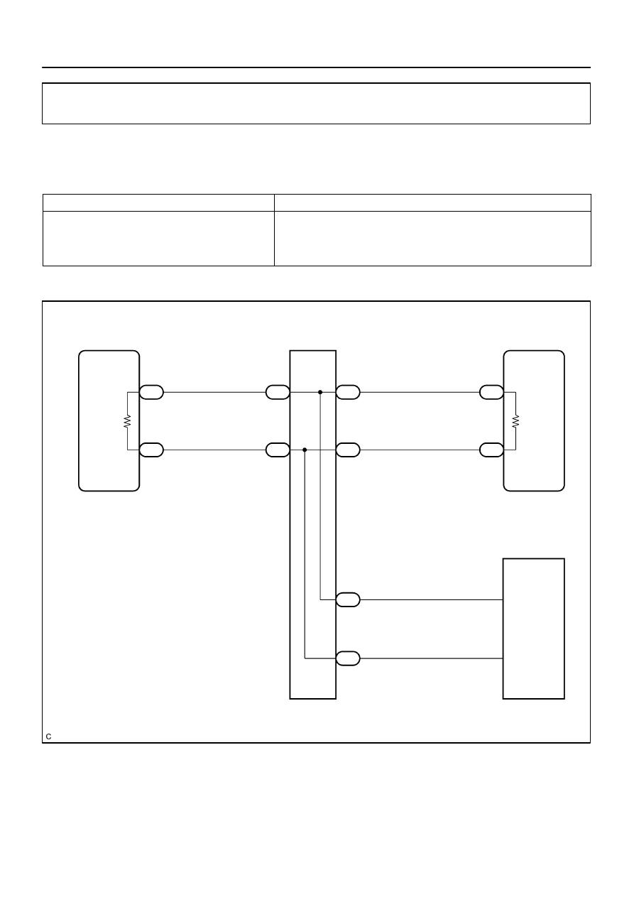
F19701
Translate ECU
ENG+
ENG–
Junction Connector
14
T5
16
T5
R
W
1
J55
2
J55
1
J53
2
J53
L
W
33
E5
34
E5
ECM
CANH
CANL
D6 DLC3
1
J54
2
J54
B
W
6
14
CANH
CANL
DI–1086
–
DIAGNOSTICS
CAN COMMUNICATION SYSTEM
1280
Check CAN Main Bus Line For Disconnection
CIRCUIT DESCRIPTION
The CAN main bus line and DLC3 sub bus line may have a disconnection when the resistance between ter-
minals 6 (CANH) and 14 (CANL) of the DLC3 is more than 69
Ω
.
Symptom
Trouble Area
Resistance between terminals 6 (CANH) and 14 (CANL) of
the DLC3 is more than 69
Ω
.
CAN main bus line
ECM
Translate ECU
DLC3 sub bus line
WIRING DIAGRAM
DIDIC–01
Нет комментариевНе стесняйтесь поделиться с нами вашим ценным мнением.
Текст