Toyota Sequoia (2005). Manual — part 60

DID7Y–01
D13872
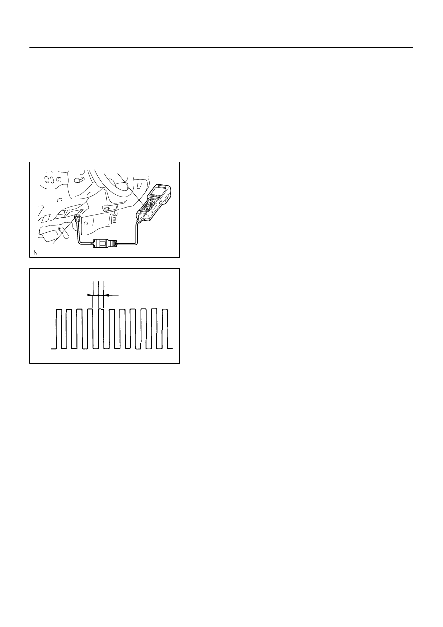
Hand–Held Tester
DLC3
CAN VIM
–
DIAGNOSTICS
ENGINE
DI–43
237
DTC CHECK / CLEAR
1.
CHECK DTC
DTCs which are stored in the ECM can be displayed with the
hand–held tester or generic OBD II scan tool.
These scan tools can display pending DTCs and current DTCs.
Some DTCs are not stored if the ECM does not detect a mal-
function during consecutive driving. However, the detected
malfunction during once driving is stored as pending DTC.
(a)
Connect the hand–held tester to the CAN VIM. Then con-
nect the CAN VIM to the Data Link Connector 3 (DLC3).
(b)
Turn the ignition switch to ON.
(c)
Enter the following menus: DIAGNOSIS / ENHANCED
OBD II / DTC INFO / CURRENT CODES (or PENDING
CODE).
(d)
Confirm the DTCs and freeze frame data and then write
them down.
(e)
to confirm the details of the DTCs.
NOTICE:
When simulating a symptom with the hand–held tester to
check the DTCs, use the normal mode. For DTC chart sub-
ject to ”2 trip detection logic”, perform either of the follow-
ing actions.
Turn the ignition switch OFF after the symptom is simulated
once. Then repeat the simulation process again. When the
problem has been simulated twice, the MIL illuminates and the
DTCs are recorded in the ECM.
2.
CLEAR DTC
(a)
Connect the hand–held tester to the CAN VIM. Then con-
nect the CAN VIM to the DLC3.
(b)
Turn the ignition switch to ON.
(c)
Enter the following menus: DIAGNOSIS / ENHANCED
OBD II / DTC INFO / CLEAR CODES and press YES.
DID7Z–01
D13872
Hand–Held Tester
DLC3
CAN VIM
BR3904
0.13 sec.
0.13 sec.
ON
OFF
DI–44
–
DIAGNOSTICS
ENGINE
238
CHECK MODE PROCEDURE
HINT:
Hand–held tester only:
Check mode has a higher sensitivity to detect malfunctions and
can detect malfunctions that normal mode cannot detect.
Check mode can also detect all the malfunctions that normal
mode can detect.
1.
CHECK MODE PROCEDURE
(a)
Make sure that the items below are true.
(1)
Battery positive voltage 11 V or more
(2)
Throttle valve fully closed
(3)
Transmission in the P or N position
(4)
A/C switched OFF
(b)
Turn the ignition switch OFF.
(c)
Connect the hand–held tester to the DLC3.
(d)
Turn the ignition switch ON.
(e)
Change the ECM to check mode with the hand–held tes-
ter. Enter the following menus: DIAGNOSIS / EN-
HANCED OBD II / CHECK MODE. Make sure the MIL
flashes as shown in the illustration.
NOTICE:
All DTCs and freeze frame data recorded will be erased if:
1) the hand–held tester is used to change the ECM from
normal mode to check mode or vice–versa; or 2) during
check mode, the ignition switch is turned from ON to ACC
or OFF.
(f)
Start the engine. The MIL should turn off after the engine
starts.
(g)
Simulate the conditions of the malfunction described by
the customer.
(h)
After simulating the malfunction conditions, use the
hand–held tester diagnosis selector to check the DTC,
freeze frame data and other data.
(i)
After checking the DTC, inspect the applicable circuit.
2.
CLEAR DTC (Using the hand–held tester)
(a)
Connect the OBD ll scan tool or the hand–held tester to
the DLC3.
(b)
Turn the ignition switch ON.
(c)
Erase DTCs and freeze frame data with the OBD II scan
tool (complying with SAE J1978) or the hand–held tester.
For the hand–held tester: 1) enter the following menus:
DIAGNOSIS / ENHANCED OBD II / DTC INFO / CLEAR
CODES; and 2) press YES. For the OBD II scan tool, see
its instruction manual.
–
DIAGNOSTICS
ENGINE
DI–45
239
3.
CLEAR DTC (Not using the hand–held tester)
(a)
Remove the EFI No. 1 and ETCS fuses from the engine
room J/B for more than 60 seconds, or disconnect the bat-
tery terminal for more than 60 seconds.
After disconnecting the battery terminal, perform the ”INI-
TIALIZE” procedure.

DID80–01
DI–46
–
DIAGNOSTICS
ENGINE
240
FAIL–SAFE CHART
If any of the following code is recorded, the ECM enters fail–safe mode.
DTC No.
Fail–Safe Operation
Fail–Safe Deactivation Conditions
P0031
P0032
P0037
P0038
P0051
P0052
P0057
P0058
The heater circuit in which an abnormality is detected is
turned off
Ignition switch OFF
P0100
P0102
P0103
Ignition timing is calculated from engine speed and throttle
angle
”Pass” condition detected
P0110
P0112
P0113
Intake air temperature is fixed at 20°
C
(68°
F
)
”Pass” condition detected
P0115
P0117
P0118
Engine coolant temperature is fixed at 80°
C
(176°
F
)
”Pass” condition detected
P0120
P0121
P0122
P0123
P0220
P0222
P0223
P0607
P0657
P2102
P2103
P2111
P2112
P2118
P2119
P2135
If the Electronic Throttle Control System (ETCS) has a mal-
function, the ECM cuts off current to the throttle control
motor. The throttle control valve returns to a predetermined
opening angle (approximately 16
) by the force of the return
spring. The ECM then adjusts the engine output by control-
ling the fuel injection (intermittent fuel–cut) and ignition tim-
ing in accordance with the accelerator pedal opening angle
to enable the vehicle to continue at a minimal speed.
If the accelerator pedal is depressed firmly and slowly, the
vehicle can be driven slowly. If the accelerator pedal is
depressed quickly, the vehicle may speed up and slow
down erratically.
”Pass” condition is detected and then the ignition switch is
turned OFF.
P0325
P0330
Max. timing retardation
Ignition switch OFF
P0351
P0352
P0353
P0354
P0355
P0356
P0357
P0358
Fuel cut
”Pass” condition detected
Нет комментариевНе стесняйтесь поделиться с нами вашим ценным мнением.
Текст