Toyota Sequoia (2005). Manual — part 108

–
DIAGNOSTICS
ENGINE
DI–235
429
MONITOR DESCRIPTION
The air injection driver (AID) detects an open or short in the circuit according to the voltage of the air pump
terminal (VP) and electromagnetic air switching valve terminal (VV), and sends a signal as diagnostic in-
formation to the ECM.
The AID outputs the air switching valve terminal malfunction signal to the ECM if: 1) VV terminal voltage is
low despite the AID receiving the command signal from the ECM to drive the air switching valve terminal or
2) VV terminal voltage is high despite the AID not receiving the command signal from the ECM.
The ECM stores the DTC based on the diagnostic signal from the AID and illuminates the MIL.
MONITOR STRATEGY
Related DTCs
P0412
Air switching valve circuit malfunction (Second-
ary air injection system)
Required sensors/components
Air injection driver, Air switching valve
Frequency of operation
Continuous
Duration
3 sec.
MIL operation
Immediate
Sequence of operation
None
TYPICAL ENABLING CONDITIONS
It
Specification
Item
Minimum
Maximum
The monitor will run whenever this DTC is
not present
See page
Case 1:
Air pump
Operating
Air switching valve
Operating
Battery voltage
8 V
–
Ignition switch
ON
Starter
OFF
Case 2:
Air pump
Not operating
Air switching valve
Not operating
Battery voltage
8 V
–
Ignition switch
ON
Starter
OFF
TYPICAL MALFUNCTION THRESHOLDS
Detection Criteria
Threshold
Case 1, 2:
Diagnostic signal duty ratio from air injection driver
31 to 48 %
COMPONENT OPERATING RANGE
Parameter
Standard Value
Diagnostic signal duty ratio from air injection driver
70 to 90% when secondary air injection system operating
and
0% when secondary air injection system not operating
A23551
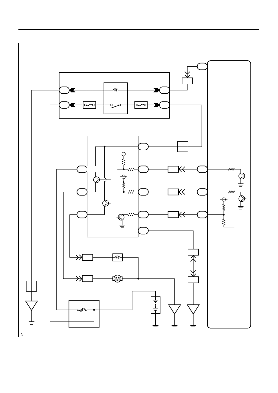
Engine Room J/B
ECM
E4
E4
E4
E4
B–W
IA4
IA4
IA4
IA4
IA4
EB4
ED2
ED2
B–W
2H
2A
6
8
EFI Relay
2
1
2F
1
W–B
J5
J/C
A
ED
Battery
Air Pump
Air Switching Valve
Air Injection Driver
A43
A46
A41
5
G–R
G–R
J2
J/C
A
A
EFI No.2
EFI No.1
3
5
2
2D
1
B
4
F10
FL Block
5
B
L
A40
1
EN
B
B
B
1
1
2
2
W
W–L
W–L
W
3
4
2
6
A40
A41
A41
A41
A41
A41
1
2
4
3
1
8
EB
W–B
W–B
W–B
BATT
VP
VV
E
SIP
DI
SIV
+B
R–W
R–W
8
3
9
G–W
G–W
GR–L
GR–L
4
25
13
AID
AIRP
AIRV
A/PUMP
2
MREL
DI–236
–
DIAGNOSTICS
ENGINE
430
WIRING DIAGRAM
B17411
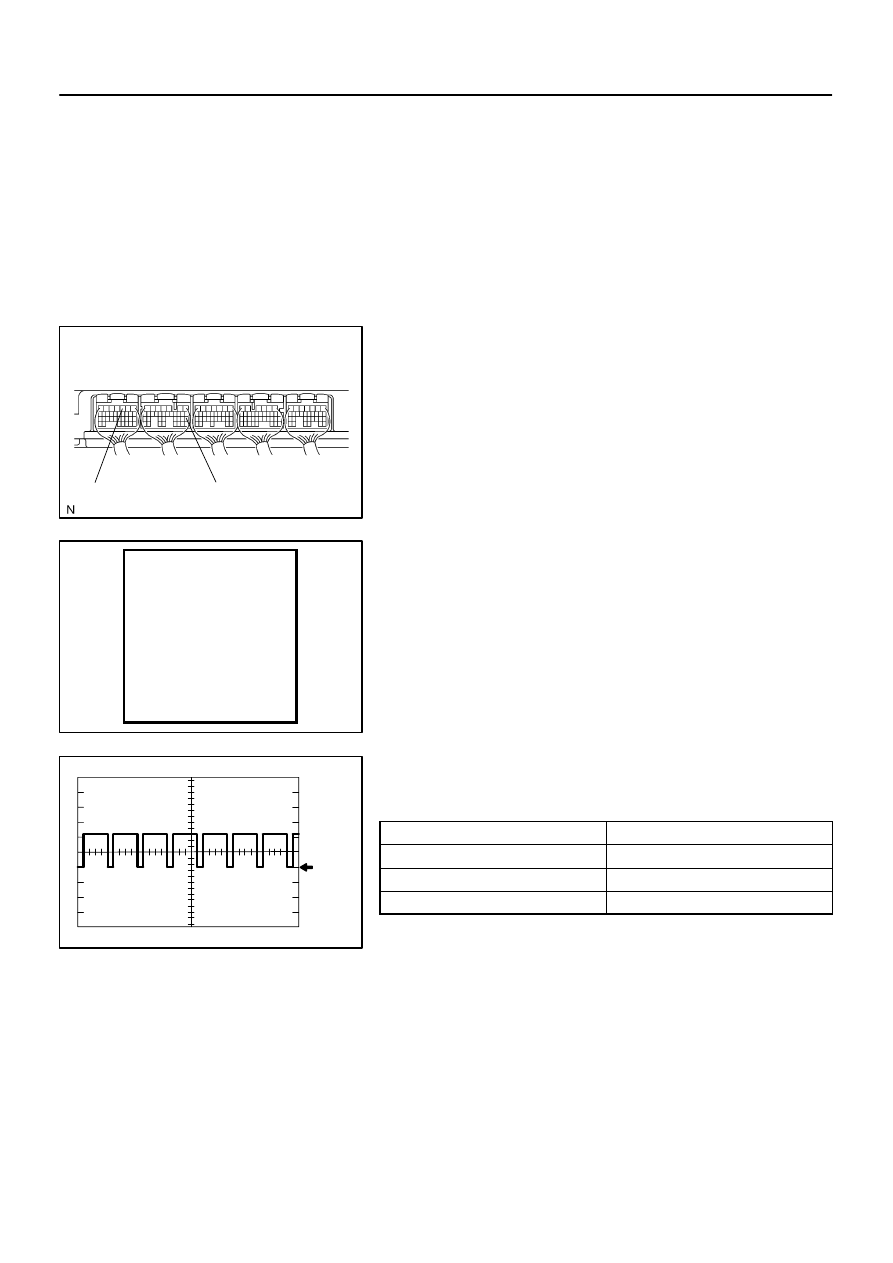
ECM Connector
E1
AIDI
A16555
AIR INJ CHECK
AIR PUMP. . . . . . . ON
EASV . . . . . . . OPEN
ASV1. . . . . . . . .OPEN
ASV2. . . . . . . ...OPEN
A/F BANK1. . . . . ...19.05
A/F BANK2. . . . . ...19.05
PRESSURE. . . . . 17 kPa
PULSATION. . . ..25.39 kPa
AI STATUS. . . . . . ...OK
Remaining Time 05 sec.
Press [EXIT] to quit
Example: 80% Duty Signal
5 V/DIV.
GND
20 ms/DIV.
–
DIAGNOSTICS
ENGINE
DI–237
431
INSPECTION PROCEDURE
HINT:
The diagnostic information output from the AID can be confirmed by connecting an oscilloscope to the diag-
nostic information terminal of the AID. It narrows the trouble area to read the waveform on the oscilloscope
when performing the AI system intrusive operation function provided in the SYSTEM CHECK.
(1)
Start the engine and warm it up.
(2)
Turn the ignition switch to OFF.
(3)
Connect a hand–held tester to the DLC3.
(4)
Connect an oscilloscope probe to the AIDI terminal
of the ECM.
(5)
Start the engine and turn the tester ON.
(6)
On the tester, select the following menu items:
DIAGNOSIS / ENHANCED OBD II / SYSTEM
CHECK / AIR INJ CHECK / MANUAL OPERATION
/ OPERATION 1 and 2.
HINT:
OPERATION 1: AP: OFF, EASV:CLOSE, ASV1:CLOSE,
ASV2:CLOSE
OPERATION 2: AP: ON, EASV:OPEN, ASV1:OPEN,
ASV2:OPEN
(7)
Monitor the voltage output of the AID (duty ratio sig-
nal).
Oscilloscope range:
Items
Contents
Terminals
CH1: AIDI – E1
Equipment Settings
5 V/Division, 20 to 40 ms/Division
Conditions
Idling
NOTICE:
This AIR INJECTION CHECK only allows technicians to operate the AI system for 5 seconds.
Furthermore, the check can be performed 4 times a trip. If the test is repeated, intervals of at
least 30 seconds are required between checks.
While the AI system operation using the hand–held tester is prohibited, the tester displays the
prohibition (WAIT or ERROR). If the ERROR (AI STATUS NG) is displayed on the tester, stop the
engine for 10 minutes and then try again.
Performing the AIR INJ CHECK over and over again may cause the damage in the secondary
air injection system. If necessary, put an interval of several minutes between tests to prevent
overheating the system.
A23464
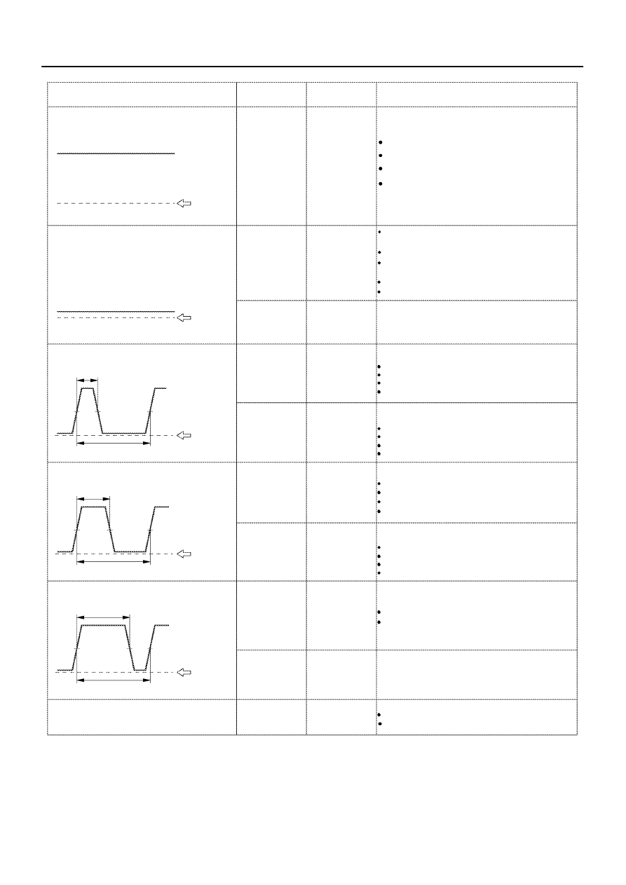
AID Diagnostic Signal Waveforms
ECM
Commands
DTCs
Suspected Trouble Areas
(ECM Output)
100 % Duty ratio
+B
Almost Battery Voltage
GND
0 % Duty ratio
+B
Fixed at Low Voltage
GND
20 % Duty ratio
20 %
+B
GND
40 % Duty ratio
40 %
+B
GND
80 % Duty ratio
80 %
+B
GND
Excluding above
(excluding 0, 20, 40, 80, 100 % duty)
Air Pump: ON
Air Pump: OFF
ASV: ON
ASV: OFF
AI System: OFF
(Air pump OFF,
ASV OFF)
AI System: ON
(Air pump ON,
ASV ON)
P1613
P0418
P0418
P0412
P0412
P1613
P1613
Air Injection Control Driver (AID)
Open in AID+B circuit (AID power source)
Open or short in air pump or Air Switching Valve
AID
ECM
Open in air pump drive circuit (AID–Pump) ,
Harness & connector (AID–Pump)
Air Pump
AID
ECM
Short between air pump drive circuit and body ground
AID
ECM
Harness & connector (AID–Pump)
Air Pump
Open in ASV drive circuit (AID–ASV),
Harness & connector (AID–ASV)
ASV
AID
ECM
Short between ASV drive circuit and body ground
Harness & connector (AID–ASV)
AID
ECM
ECM
Normal
AID
AID
or short between air pump drive circuit and +B
or short between ASV drive circuit and +B
ASV
–
AI System: OFF
(Air pump OFF,
ASV OFF)
AI System: ON
(Air pump ON,
ASV ON)
Normal
Any Air Injection
(AI) System op-
eration
P1613
Open in AID ground circuit
Short between +B circuit and diagnostic signal circuit
Short between diagnostic signal circuit and body
(ASV) command signal circuit (ECM–AID)
ground
Open in AID ground circuit
Open in diagnostic signal circuit
DI–238
–
DIAGNOSTICS
ENGINE
432
Нет комментариевНе стесняйтесь поделиться с нами вашим ценным мнением.
Текст