Toyota Sequoia (2005). Manual — part 361
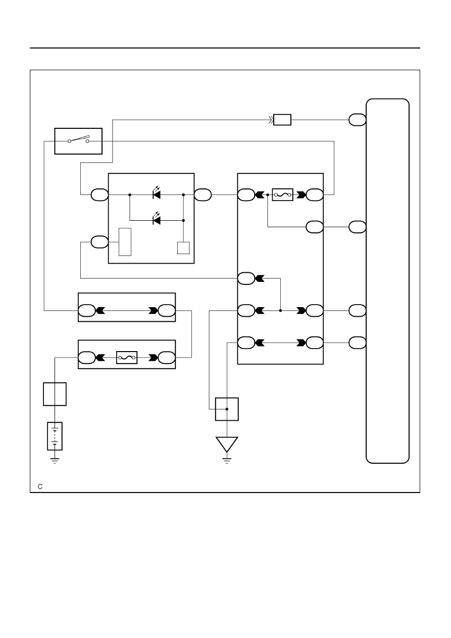
H23995
RMIL
A20
20
IM1
B–R
I18
Ignition SW
Combination Meter
Battery
IG2
A20
21
E1
A20
25
E2
A20
26
B
W–B
W–B
B–R
IG2
AM2
6
5
W–R
RSCA OFF
B–R
C5
40
C6
12
C6
24
1H
11
1C
2
1A
3
IGN1
1D
6
1F
9
1F
10
1A
6
1A
8
Instrument Panel J/B
Engine Room J/B
1C
3
1J
7
2C
1
2D
1
AM2
BR
W–B
W–B
J8
J/C
A
A
F10
Fusible Link Block
4
5
B
B
B–O
IE
Airbag Sensor
Assembly
1
W–R
–
DIAGNOSTICS
SUPPLEMENTAL RESTRAINT SYSTEM
DI–1239
1433
WIRING DIAGRAM
DI–1240
–
DIAGNOSTICS
SUPPLEMENTAL RESTRAINT SYSTEM
1434
INSPECTION PROCEDURE
1
Check RSCA OFF indicator condition.
CHECK:
Turn the ignition switch to the ON position, check the RSCA OFF indicator condition.
RESULT:
The RSCA OFF indicator does not come on when the RSCA OFF switch is
operate (remains off).
A
The RSCA OFF indicator remains on when the RSCA OFF switch is not
operate (remains on).
B
B
Go to step 7.
A
2
Prepare for inspection.
PREPARATION:
CAUTION:
Be sure to perform the following procedures before troubleshooting to avoid unexpected airbag de-
ployment.
(a)
Turn the ignition switch LOCK position.
(b)
Disconnect the negative (–) terminal cable from the battery, and wait for at least 90 seconds.
(c)
Disconnect the connectors from the airbag sensor assembly.
(d)
Disconnect the connectors from the steering wheel pad.
(e)
Disconnect the connectors from the front passenger airbag assembly.
(f)
w/ Side and curtain shield airbag:
Disconnect the connectors from the side airbag assembly LH and RH.
(g)
w/ Side and curtain shield airbag:
Disconnect the connectors from the curtain shield airbag assembly LH and RH.
(h)
Disconnect the connectors from the front seat outer belt LH and RH.
NEXT
I28570
C6
C6–24
–
DIAGNOSTICS
SUPPLEMENTAL RESTRAINT SYSTEM
DI–1241
1435
3
Check battery.
CHECK:
Measure the voltage of the battery.
OK:
Voltage: 11 to 14 V
NG
Replace battery.
OK
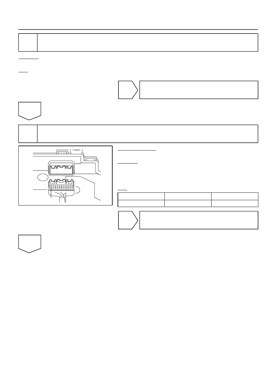
4
Check combination meter (source voltage).
PREPARATION:
Disconnect the connector from the combination meter.
CHECK:
(a)
Turn the ignition switch to the ON position.
(b)
Measure the voltage according to the value(s) in the table
below.
OK:
Tester Connection
Condition
Specified Condition
C6–24 – Body ground
Ignition switch ON
8 to 14 V
NG
Repair or replace wire harness (combination
meter – battery).
OK
H01015
G27651
H23985
RMIL
Airbag
Sensor
Assembly
A
Cowl Wire
Combination
Meter
A20
B
C
D
DI–1242
–
DIAGNOSTICS
SUPPLEMENTAL RESTRAINT SYSTEM
1436
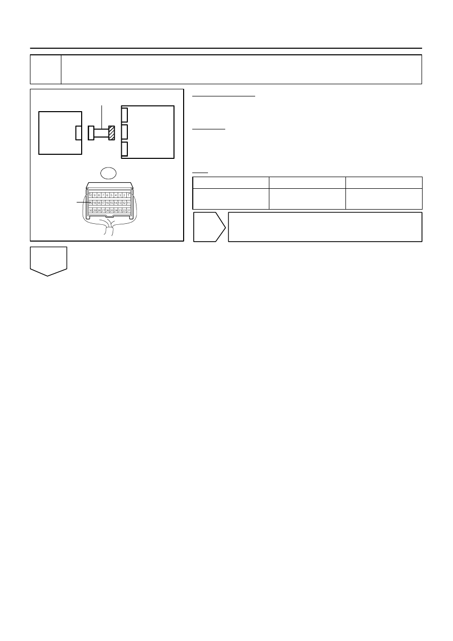
5
Check cowl wire (short to B+).
PREPARATION:
Connect the negative (–) terminal cable to the battery, and wait
for at least 2 seconds.
CHECK:
(a)
Turn the ignition switch to the ON position.
(b)
Measure the voltage according to the value(s) in the table
below.
OK:
Tester Connection
Condition
Specified Condition
A20–20 (RMIL) –
Body ground
Ignition switch ON
Below 1 V
NG
Repair or replace cowl wire.
OK
Нет комментариевНе стесняйтесь поделиться с нами вашим ценным мнением.
Текст