Toyota Sequoia (2005). Manual — part 604

–
DIAGNOSTICS
NAVIGATION SYSTEM
DI–2211
2405
D7
*2
Connection Check Error
Component in which this code is recorded has
been disconnected from system after engine start.
Or, when this code was recorded, RSA panel was
disconnected.
1. Power source circuit (radio and
navigation assy).
2. AVC–LAN (Radio and navigation
assy – Rear seat audio control-
ler).
3. Replace Rear seat audio control-
ler.
–
DC
*1
*3
Transmission Error
Transmission to component shown by sub–code
has been failed.
(This code does not necessarily mean actual fail-
ure.)
If same sub–code is recorded in
other component(s), check harness
for power supply and communica-
tion system of all components
shown by code.
–
DD
*4
Master Reset (Momentary Inter-
ruption)
Component that is to be master has been discon-
nected after engine start.
1. Power source circuit (radio and
navigation assy).
2. AVC–LAN (Radio and navigation
assy – Rear seat audio control-
ler).
3. Replace Rear seat audio control-
ler.
–
E0
*1
Registration Completion
Instruction Error
”Registration Completion Instruction” command
from master cannot be received.
Since this DTC is provided for engi-
neering, it may be detected when no
actual failure exists.
–
E3
*1
Registration Request Transmis-
sion
Registration Request command is output from
slave component.
Registration Request command is output from
sub–master component.
Since this DTC is provided for engi-
neering, it may be detected when no
actual failure exists.
–
DF
*4
Master Error
Due to defective condition of component with a
display, master function is switched to audio
equipment.
Error occurs in communication between sub–
master (audio) and master component.
1. Power source circuit (radio and
navigation assy).
2. AVC–LAN (Radio and navigation
assy – Rear seat audio control-
ler).
3. Replace Rear seat audio control-
ler.
–
E4
*1
Multiple Frame Abort
Multiple frame transmission is aborted.
Since this DTC is provided for engi-
neering purpose, it may be detected
when no actual failure exists.
–
D8
*2
No Response To Connection
Check
Component shown by sub–code is or had been
disconnected from system after engine start.
1. Power source circuit (radio and
navigation assy).
2. AVC–LAN (Radio and navigation
assy – Rear seat audio control-
ler).
3. Replace Rear seat audio control-
ler.
–
D9
*1
Last Mode Error
Component operated (sound and/or image was
provided) before engine stop is or was discon-
nected with ignition switch in ACC or ON.
1. Power source circuit (radio and
navigation assy).
2. AVC–LAN (Radio and navigation
assy – Rear seat audio control-
ler).
3. Replace Rear seat audio control-
ler.
–

DI–2212
–
DIAGNOSTICS
NAVIGATION SYSTEM
2406
DA
No Response to ON/OFF
Instruction
No response is identified when changing mode
(audio and visual mode change).
Detected when sound and picture does not
change by button operation
1. Power source circuit (radio and
navigation assy).
2. AVC–LAN (Radio and navigation
assy – Rear seat audio control-
ler).
3. Replace Rear seat audio control-
ler.
–
DB
*1
Mode Status Error
Dual alarm is detected.
1. Power source circuit (radio and
navigation assy).
2. AVC–LAN (Radio and navigation
assy – Rear seat audio control-
ler).
3. Replace Rear seat audio control-
ler.
–
DE
*4
Slave Reset (Momentary Inter-
ruption)
After engine start, slave component has been dis-
connected.
1. Power source circuit (radio and
navigation assy).
2. AVC–LAN (Radio and navigation
assy – Rear seat audio control-
ler).
3. Replace Rear seat audio control-
ler.
–
HINT:
*1: Even if no failure is detected, this code may be stored depending on the battery condition or voltage
for starting the engine.
*2: When 210 sec. has passed after pulling out the power supply connector of the master component
with the ignition switch in ACC or ON, this code is stored.
*3: This code may be stored when the engine key is turned 1 min. again after engine start.
*4: This code may be stored when the engine key is turned again after engine start.
DIDC8–01
–
DIAGNOSTICS
NAVIGATION SYSTEM
DI–2213
2407
CIRCUIT INSPECTION
Pressing power switch does not turn on system
INSPECTION PROCEDURE
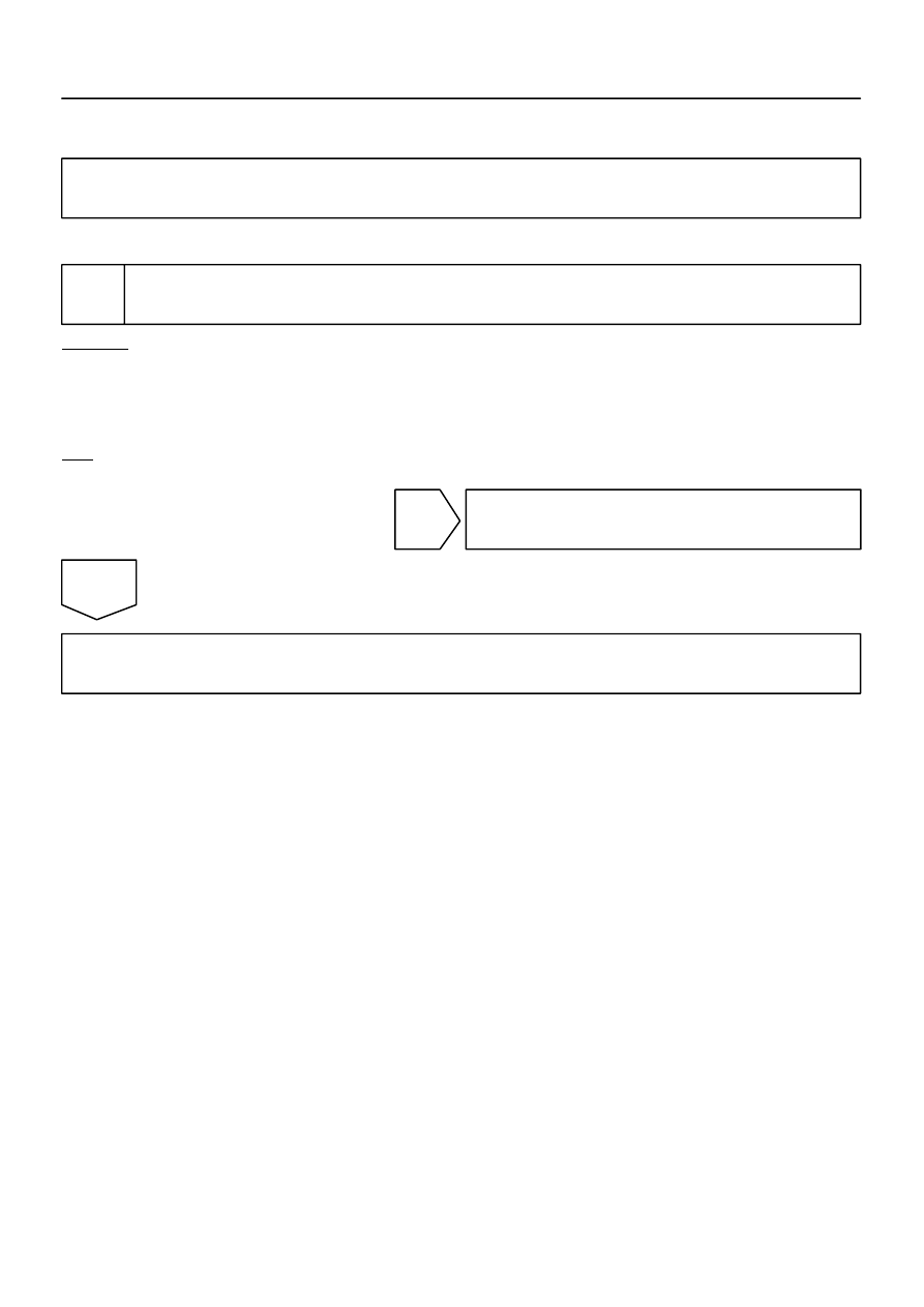
1
Check cabin.
CHECK:
Check that conditions in the cabin are not likely to cause condensation.
HINT:
This problem occurs when the cabin is humid and the temperature rapidly changes. This condition may pro-
duce condensation, resulting in a short circuit.
OK:
Condensation is not likely.
NG
Dry cabin and recheck conditions.
OK
Proceed to next circuit inspection shown in problem symptoms table (See page
DI–2214
–
DIAGNOSTICS
NAVIGATION SYSTEM
2408
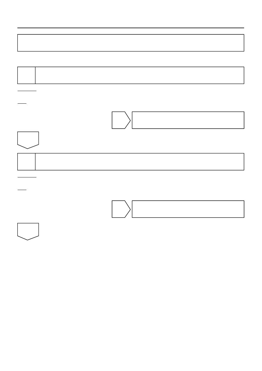
Black screen (No image appears on navigation and audio screen)
INSPECTION PROCEDURE
1
Check display setting.
CHECK:
Check that the display is not in ”Screen OFF” mode.
OK:
The display setting is not in ”Screen OFF” mode.
NG
Change screen to ”screen on” mode.
OK
2
Check image quality setting.
CHECK:
Check if screen color quality can be set.
OK:
Screen color quality can be set.
OK
Press panel switch ”display” and set screen
color quality to normal.
NG
DIDC9–01
Нет комментариевНе стесняйтесь поделиться с нами вашим ценным мнением.
Текст