Toyota Sequoia (2005). Manual — part 870
I28731
10
1
2
7
BE2MP–01
I18596
I18689
Wire Harness Side:
I18559
1
4
5
2
3
–
BODY ELECTRICAL
DEFOGGER SYSTEM
BE–65
3469
INSPECTION
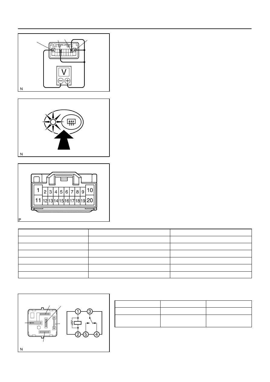
1.
Connecter connected:
INSPECT DEFOGGER TIMER OPERATION
(a)
Connect the positive (+) lead from the voltmeter to termi-
nals 1, 2 and 7 of the panel switch connector and the neg-
ative (–) lead to terminal 10.
(b)
When the switch is OFF, the voltage should be approx.
12 V.
(c)
Turn the defogger switch ON and check that the indicator
comes on and that the voltage is less than 1 V.
(d)
After 15 minutes, check that the switch is OFF and the
voltage is approx. 12 V.
If operation is not as specified, replace the switch.
2.
Connector disconnected:
INSPECT DEFOGGER SWITCH (in INTEGRATION
CONTROL PANEL SWITCH) CIRCUIT
Disconnect the connector from the panel switch and inspect the
connector on the wire harness side, as shown in the chart be-
low.
Tester connection
Condition
Specified condition
10 – Ground
Always
Continuity
1 – Ground
Always
Battery voltage
2 – Ground
Ignition switch OFF or ACC
No voltage
2 – Ground
Ignition switch ON
Battery voltage
7 – Ground
Ignition switch OFF
No voltage
7 – Ground
Ignition switch ACC or ON
Battery voltage
If the circuit is not as specified, inspect the circuit connected to
other parts.
3.
INSPECT DEFOGGER RELAY CONTINUITY
Condition
Tester connection
Specified condition
Constant
1 – 2, 3 – 4
Continuity
Apply B+ between
terminals 1 and 2.
3 – 5
Continuity
If continuity is not as specified, replace the relay.
I05027
2
1
3
5
2
5
1
3
5
I01291
Tester Probe
Tin Foil
Heat Wire
I01292
At Center
I01293
0 Volts
Broken
Wire
Several
Volts
Battery
Side
Ground Side
Foil Strip
BE–66
–
BODY ELECTRICAL
DEFOGGER SYSTEM
3470
4.
INSPECT MIRROR HEATER RELAY CONTINUITY
Condition
Tester connection
Specified condition
Always
1 – 2
Continuity
Always
3 – 5
No continuity
Apply B+ between
terminals 1 and 2.
3 – 5
Continuity
If continuity is not as specified, replace the relay.
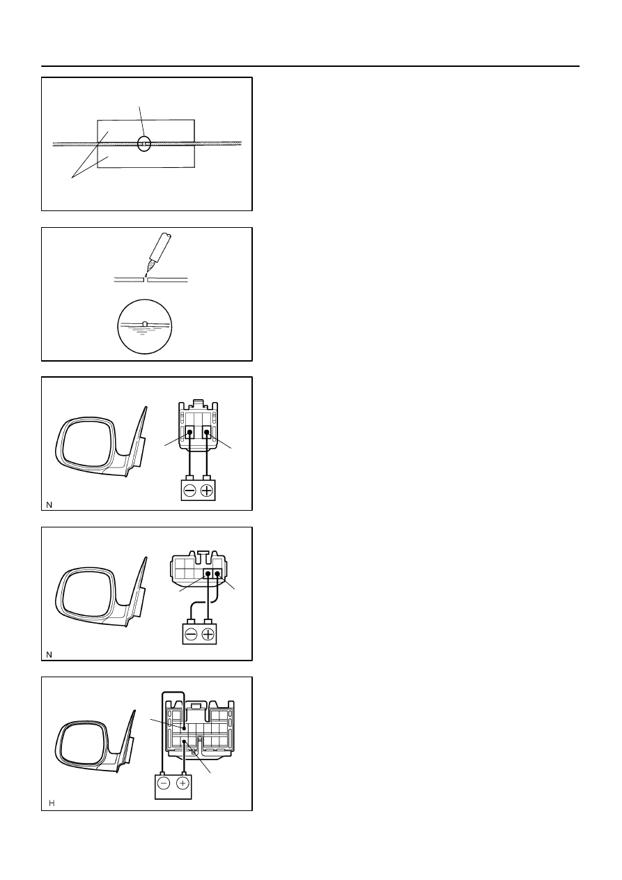
5.
INSPECT DEFOGGER WIRE
NOTICE:
When cleaning the glass, use a soft, dry cloth, and
wipe the glass in the direction of the wire. Take care
not to damage the wires.
Do not use detergents or glass cleaners with abrasive
ingredients.
When measuring voltage, wrap a piece of tin foil
around the tip of the negative probe and press the foil
against the wire with your finger, as shown in the il-
lustration.
(a)
Turn the ignition switch ON.
(b)
Turn the defogger switch ON.
(c)
Inspect the voltage at the center of each heat wire, as
shown.
Voltage
Criteria
Approx. 5 V
Okay (No break in wire)
Approx. 10 V or 0 V
Broken wire
HINT:
If there is approximately 10 V, the wire is broken between the
center of the wire and the positive (+) end. If there is no voltage,
the wire is broken between the center of the wire and ground.
(d)
Place the voltmeter positive (+) lead against the defogger
wire on the battery side.
(e)
Place the voltmeter negative (–) lead with the foil strip
against the wire on the ground side.
(f)
Slide the positive (+) lead from the battery to the ground
side.
(g)
The point where the voltmeter deflects from several V to
zero V is the place where the defogger wire is broken.
HINT:
If the heat wire is not broken, the voltmeter indicates 0 V at the
positive (+) end of the heat wire but gradually increases to about
12 V as the meter probe moves to the other end.
I01294
Repair Point
Broken
Wire
Masking Tape
I01295
I18583
6
4
I24872
7
8
I28509
5
12
–
BODY ELECTRICAL
DEFOGGER SYSTEM
BE–67
3471
6.
IF NECESSARY, REPAIR DEFOGGER WIRE
(a)
Clean the broken wire tips with grease, wax and silicon re-
mover.
(b)
Place the masking tape along both sides of the wire for
repair.
(c)
Thoroughly mix the repair agent (Dupont paste No.
4817).
(d)
Using a fine tip brush, apply a small amount of the agent
to the wire.
(e)
After a few minutes, remove the masking tape.
(f)
Do not repair the defogger wire for at least 24 hours.
7.
w/o Retract Mirror and Driving Position Memory:
INSPECT MIRROR HEATER OPERATION
(a)
Connect the positive (+) lead from the battery to terminal
6 and the negative (–) lead to terminal 4.
(b)
Check that the mirror becomes warm.
HINT:
It will take a short time for the mirror to become warm.
If operation is not as specified, replace the mirror.
8.
w/ Retract Mirror only:
INSPECT MIRROR HEATER OPERATION
(a)
Connect the positive (+) lead from the battery to terminal
7 and the negative (–) lead to terminal 8.
(b)
Check that the mirror becomes warm.
HINT:
It will take a short time for the mirror to become warm.
If operation is not as specified, replace the mirror.
9.
w/ Retract Mirror and Driving Position Memory:
INSPECT MIRROR HEATER OPERATION
(a)
Connect the positive (+) lead from the battery to terminal
5 and the negative (–) lead to terminal 12.
(b)
Check that the mirror becomes warm.
HINT:
It will take a short time for the mirror to become warm.
If operation is not as specified, replace the mirror.
BE03O–08
I28410
Power Window Regulator Assembly
Power Window Motor
Power Window Switch
Power Window
Regulator Assembly
Power Window Motor
Power Window Master Switch
Driver Door ECU
Ignition Switch
Instrument Panel J/B
Power Window Switch
Front Passenger Door ECU
Body ECU
(Located behind the Instrument Panel)
BE–68
–
BODY ELECTRICAL
POWER WINDOW CONTROL SYSTEM
3472
POWER WINDOW CONTROL SYSTEM
LOCATION
Нет комментариевНе стесняйтесь поделиться с нами вашим ценным мнением.
Текст