Toyota Sequoia (2005). Manual — part 391
H01003
H10600 H01075
H23352
D Squib
Spiral
Cable
Airbag
Sensor
Assembly
DTC 51
DLC3
TC
CG
F E
D C
–
DIAGNOSTICS
SUPPLEMENTAL RESTRAINT SYSTEM
DI–1359
1553
9
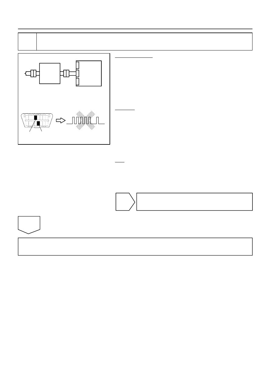
Replace steering wheel pad (D squib).
PREPARATION:
(a)
Replace the steering wheel pad (see page
HINT:
Perform the inspection using parts from a normal vehicle if pos-
sible.
(b)
Connect the connectors to the airbag sensor assembly.
(c)
Connect the negative (–) terminal cable to the battery,
and wait for at least 2 seconds.
CHECK:
(a)
Turn the ignition switch to the ON position, and wait for at
least 60 seconds.
(b)
Clear the DTCs stored in memory (see page
(c)
Turn the ignition switch to the LOCK position.
(d)
Turn the ignition switch to the ON position, and wait for at
least 60 seconds.
(e)
OK:
DTC 51 is not output.
HINT:
Codes other than DTC 51 may be output at this time, but they
are not related to this check.
NG
Replace airbag sensor assembly
(see page
).
OK
END
H01002
H23349
D Squib
Spiral
Cable
Airbag
Sensor
Assembly
C
D
E
F
DI–1360
–
DIAGNOSTICS
SUPPLEMENTAL RESTRAINT SYSTEM
1554
10
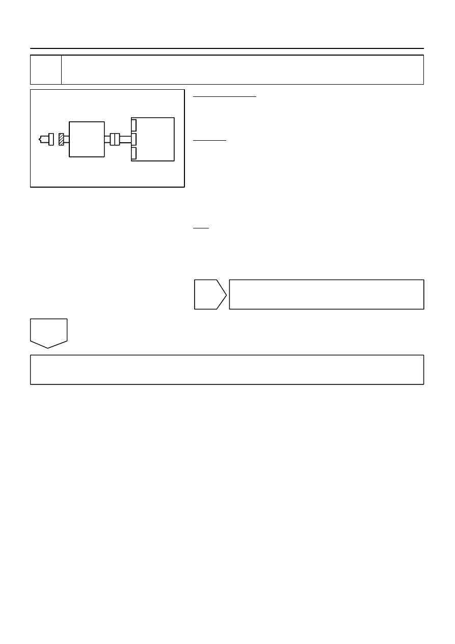
Check airbag sensor assembly.
PREPARATION:
(a)
Connect the connectors to the airbag sensor assembly.
(b)
Connect the negative (–) terminal cable to the battery,
and wait for at least 2 seconds.
CHECK:
(a)
Turn the ignition switch to the ON position, and wait for at
least 60 seconds.
(b)
Clear the DTCs stored in memory (see page
(c)
Turn the ignition switch to the LOCK position.
(d)
Turn the ignition switch to the ON position, and wait for at
least 60 seconds.
(e)
OK:
DTC B1800 is not output.
HINT:
Codes other than DTC B1800 may be output at this time, but
they are not related to this check.
NG
Replace airbag sensor assembly
(see page
OK
Go to step 12.
H23975
H01002
H23988
D Squib
D+
D–
Spiral
Cable
Color: Orange
Service Wire
C
D
E
F
Airbag
Sensor
Assembly
–
DIAGNOSTICS
SUPPLEMENTAL RESTRAINT SYSTEM
DI–1361
1555
11
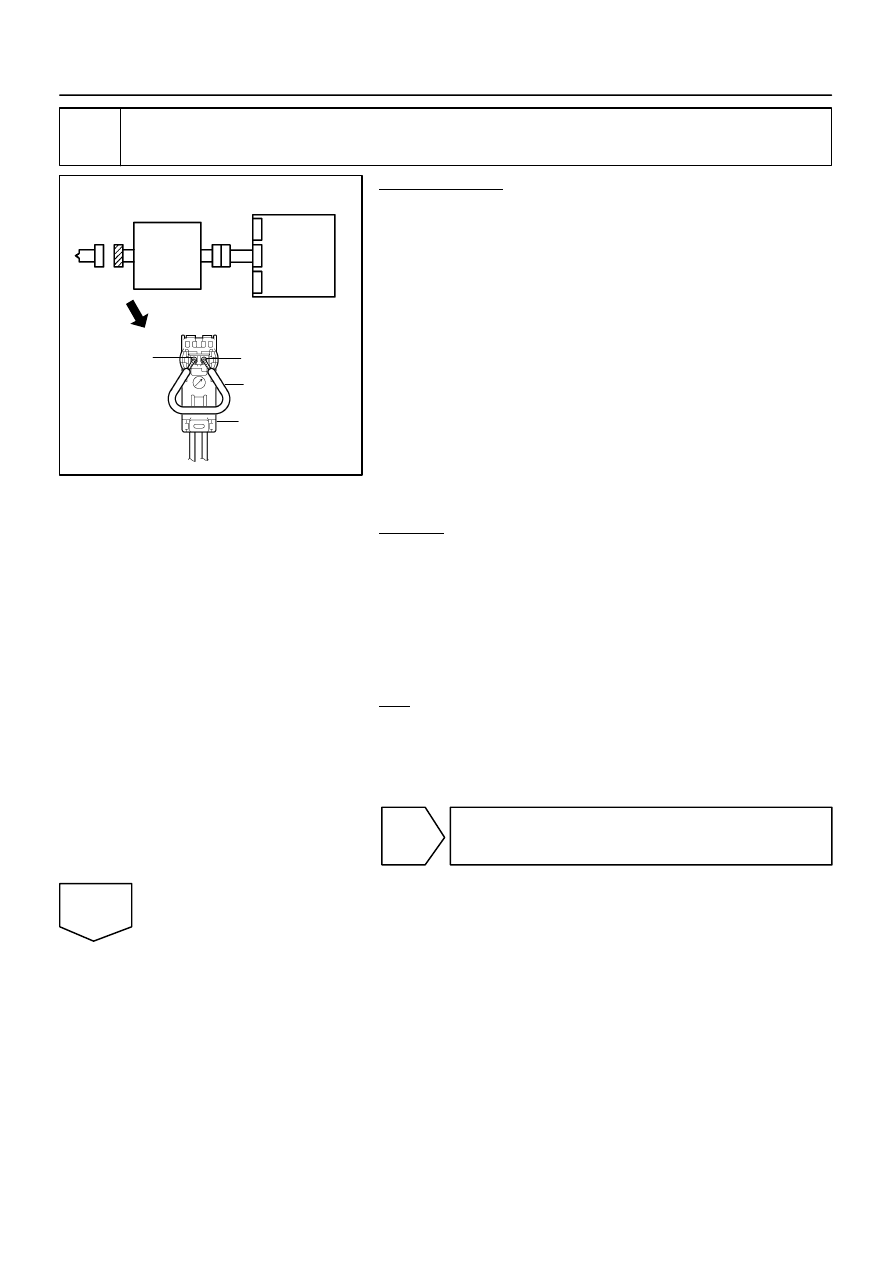
Check airbag sensor assembly.
PREPARATION:
(a)
From the step 6:
Turn the ignition switch to the LOCK position.
(b)
From the step 6:
Disconnect the negative (–) terminal cable from the bat-
tery, and wait for at least 90 seconds.
(c)
Connect the connectors to the airbag sensor assembly.
(d)
Using a service wire, connect D+ and D– of the connector
”E”.
NOTICE:
Twist the end of the service wire in order to insert it
into the connector.
Do not forcibly insert the twisted service wire into the
terminals of the connector when connecting.
(e)
Connect the negative (–) terminal cable to the battery,
and wait for at least 2 seconds.
CHECK:
(a)
Turn the ignition switch to the ON position, and wait for at
least 60 seconds.
(b)
Clear the DTCs stored in memory (see page
(c)
Turn the ignition switch to the LOCK position.
(d)
Turn the ignition switch to the ON position, and wait for at
least 60 seconds.
(e)
OK:
DTC B1801, B1802 or B1803 is not output.
HINT:
Codes other than DTC B1801, B1802 and B1803 may be out-
put at this time, but they are not related to this check.
NG
Replace airbag sensor assembly
(see page
).
OK
H01003
H23354
D Squib
Spiral
Cable
Airbag
Sensor
Assembly
C
D
E
F
DI–1362
–
DIAGNOSTICS
SUPPLEMENTAL RESTRAINT SYSTEM
1556
12
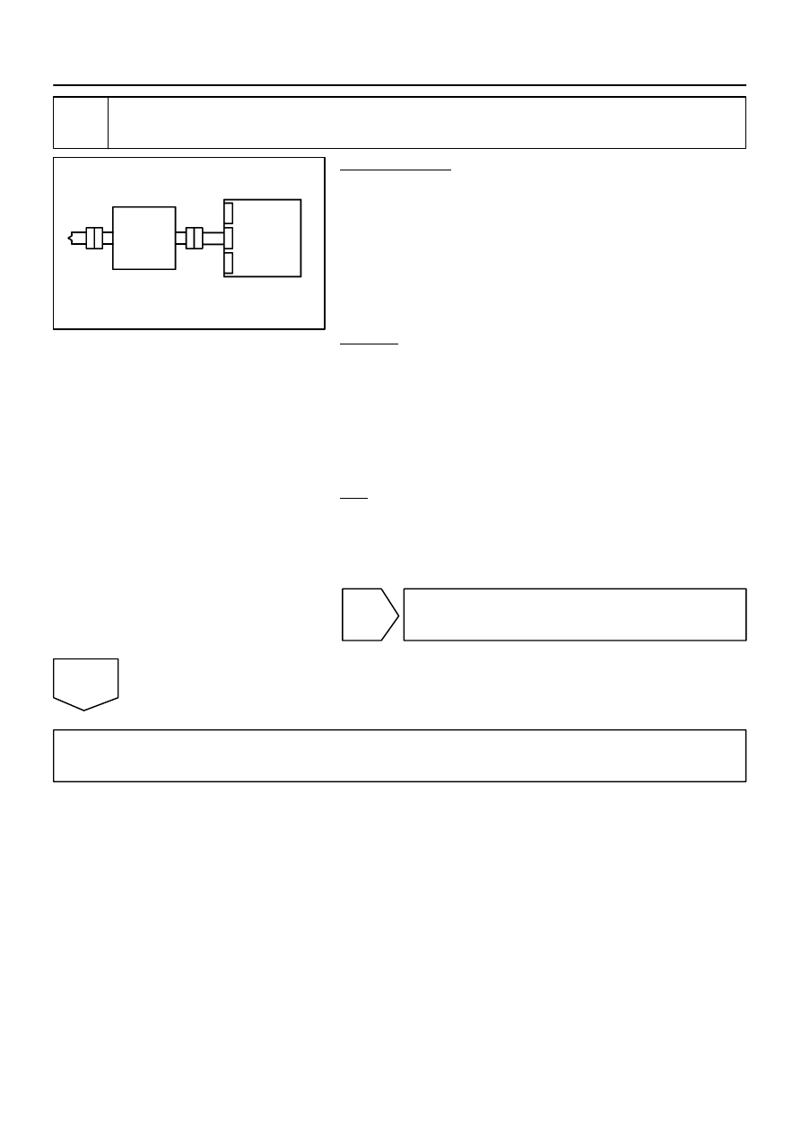
Check steering wheel pad (D squib).
PREPARATION:
(a)
Turn the ignition switch to the LOCK position.
(b)
Disconnect the negative (–) terminal cable from the bat-
tery, and wait for at least 90 seconds.
(c)
From the step 11:
Disconnect the service wire from connector ”E”.
(d)
Connect the connectors to the steering wheel pad.
(e)
Connect the negative (–) terminal cable to the battery,
and wait for at least 2 seconds.
CHECK:
(a)
Turn the ignition switch to the ON position, and wait for at
least 60 seconds.
(b)
Clear the DTCs stored in memory (see page
(c)
Turn the ignition switch to the LOCK position.
(d)
Turn the ignition switch to the ON position, and wait for at
least 60 seconds.
(e)
OK:
DTC B1800, B1801, B1802 or B1803 is not output.
HINT:
Codes other than DTC B1800, B1801, B1802 and B1803 may
be output at this time, but they are not related to this check.
NG
Replace
steering wheel pad
(see page
).
OK
From the results of the above inspection, the malfunctioning part can now be considered normal.
To make sure of this, use the simulation method to check (see page
HINT:
Perform the simulation method by selecting the check mode with the hand–held tester (see page
After selecting the check mode, perform the simulation method by wiggling each connector of the air-
bag system or driving the vehicle on a city or rough road (see page
Нет комментариевНе стесняйтесь поделиться с нами вашим ценным мнением.
Текст