Toyota Sequoia (2005). Manual — part 278
DIDM0–01
F16974
–
DIAGNOSTICS
ABS WITH EBD & BA & TRAC & VSC SYSTEM
DI–907
1101
TERMINALS OF ECU
1.
Skid Control ECU:
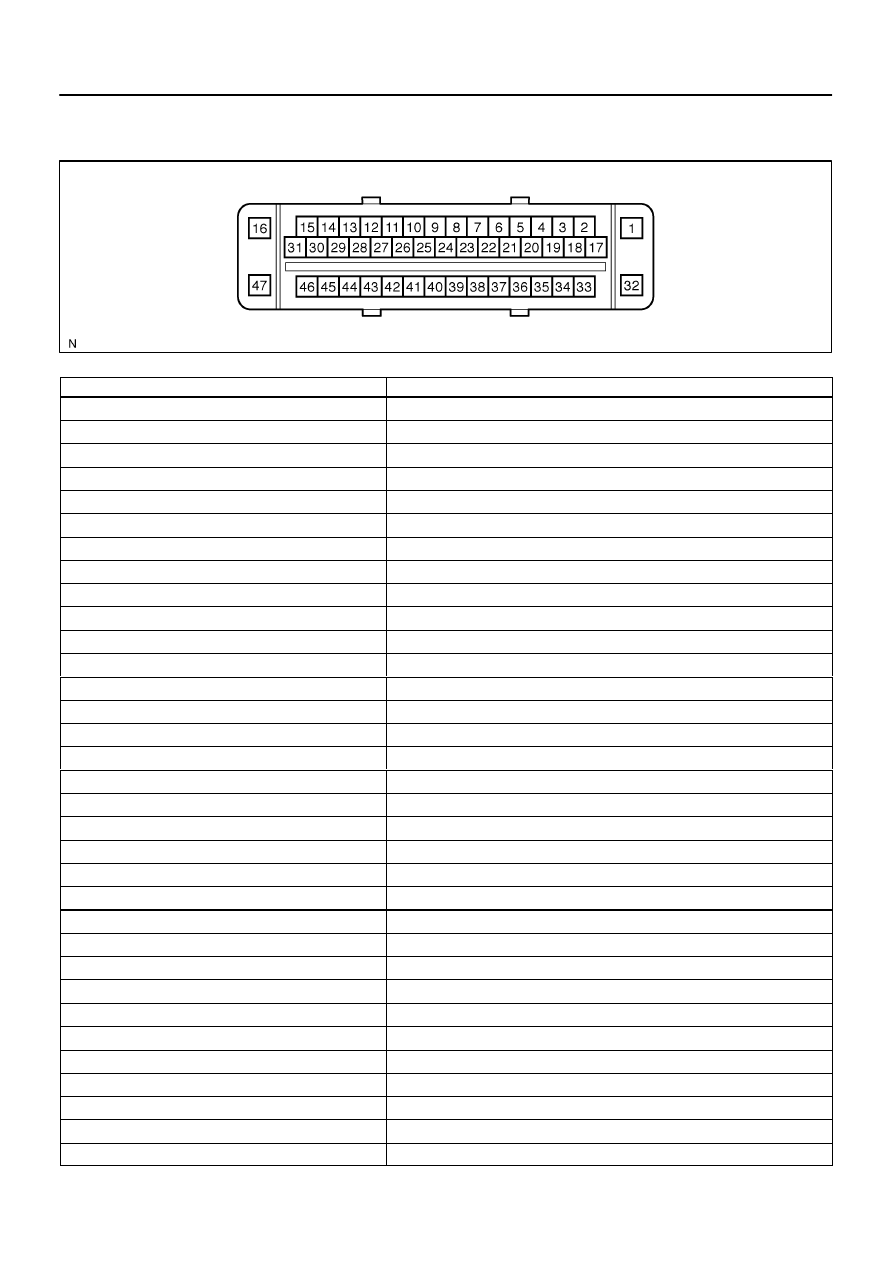
Symbols (Terminal No.)
Terminal Description
GND (1)
Skid control ECU ground
CANL (2)
Vehicle CAN communication line
VCP (3)
Pedal stroke sensor (Delta S Sensor) line
CANH (6)
Vehicle CAN communication line
E3 (8)
Pedal stroke sensor (Delta S Sensor) ground
VYS (11)
Yaw rate sensor power source
IG1 (13)
IG1 power supply
PIM (14)
Pedal stroke sensor (Delta S Sensor) line
D/G (15)
Diagnosis tester communication line
+BM (16)
Motor relay power supply
BST (17)
Brake booster line
PSNC (18)
Brake booster line
SS1 (19)
Yaw rate sensor signal line
STS (20)
Brake booster line
PSNO (21)
Brake booster line
BZ (22)
Buzzer output
SS2 (23)
Yaw rate sensor signal line
GYAW (24)
Yaw rate sensor ground
PMC2 (25)
M/C pressure sensor 2 signal
VCM2 (26)
M/C pressure sensor 2 power supply
E2 (27)
M/C pressure sensor 2 ground
PMC (28)
M/C pressure sensor 1 signal
E1 (29)
M/C pressure sensor 1 ground
VCM (30)
M/C pressure sensor 1 power supply
BSTP (31)
Brake booster line
GND2 (32)
Skid control ECU ground
FL+ (33)
FL wheel speed signal line
FL– (34)
FL wheel speed signal line
WA (35)
ABS warning light output
RR– (36)
RR wheel speed signal line
RR+ (37)
RR wheel speed signal line
BSW (38)
Brake inhibit signal line
STP (39)
Stop light switch signal input
F19198
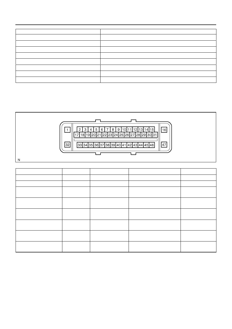
Skid Control ECU
(harness side connector)
DI–908
–
DIAGNOSTICS
ABS WITH EBD & BA & TRAC & VSC SYSTEM
1102
Symbols (Terminal No.)
Terminal Description
TS (40)
Sensor check input
+BO (41)
Steering angle sensor line
RL+ (42)
RL wheel speed signal line
RL– (43)
RL wheel speed signal line
VSCW (44)
VSC OFF indicator output
FR– (45)
FR wheel speed signal line
FR+ (46)
FR wheel speed signal line
+BS (47)
Solenoid relay power supply
2.
Terminal Inspection
Disconnect the connector and measure the voltage on the wire harness side.
HINT:
Voltage can not be measured with the connector connected to the skid control ECU as the connector is water
resistance.
Symbols (Terminal No.)
Wiring Color
Terminal Description
Condition
Specified Condition
+BM (16) – GND1, 2 (1, 32)
B–R – W–B
Motor relay power supply
IG switch ON
10 to 14 V
GYAW (24) – GND1, 2 (1, 32)
G – W–B
Yaw rate sensor ground
Always
Below 1
Ω
E3 (8) – GND1, 2 (1, 32)
L – W–B
M/C pressure sensor 3
ground
Always
Below 1
Ω
E2 (27) – GND1, 2 (1, 32)
W – W–B
M/C pressure sensor 2
ground
Always
Below 1
Ω
E1 (29) – GND1, 2 (1, 32)
W – W–B
M/C pressure sensor 1
ground
Always
Below 1
Ω
STP (39) – GND1, 2 (1, 32)
G–Y – W–B
Stop light switch signal in-
put
Brake pedal depressed
8 to 14 V
STP (39) – GND1, 2 (1, 32)
G–Y – W–B
Stop light switch signal in-
put
Brake pedal released
Below 1.5 V
+BS (47) – GND1, 2 (1, 32)
B–R – W–B
Solenoid relay power sup-
ply
IG switch ON
10 to 14 V
F16975
–
DIAGNOSTICS
ABS WITH EBD & BA & TRAC & VSC SYSTEM
DI–909
1103
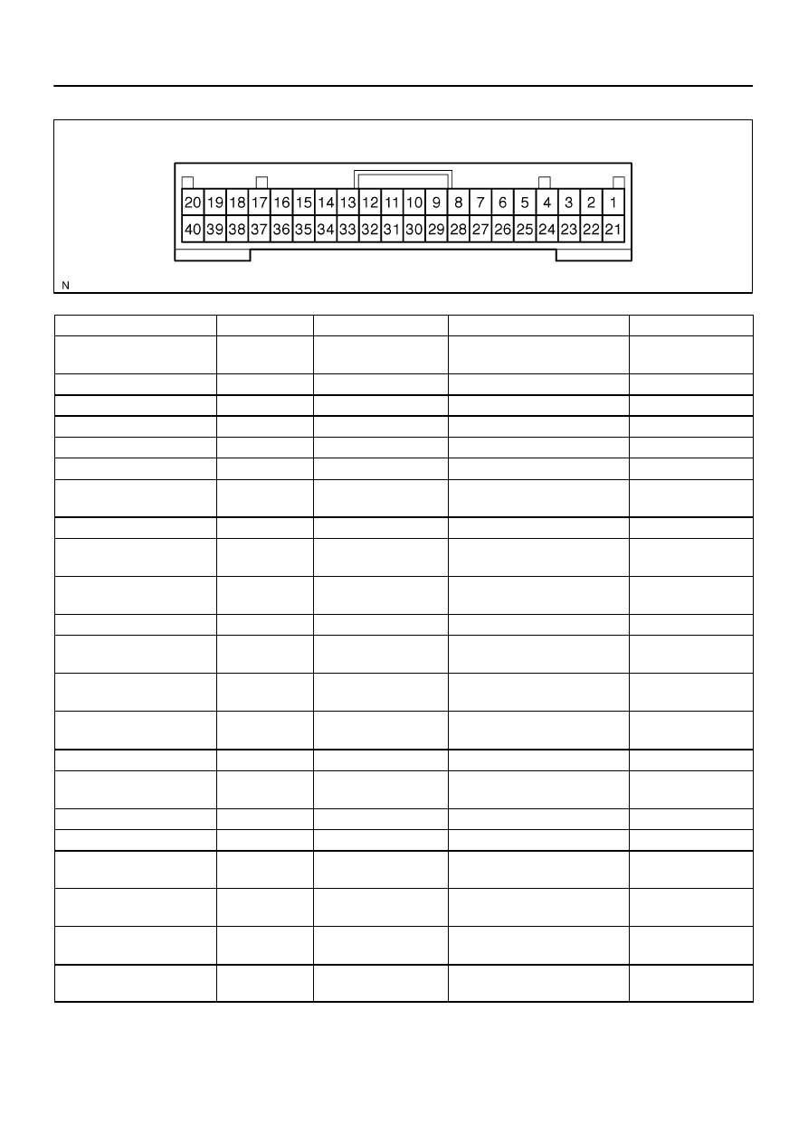
Translate ECU:
Symbols (Terminal No.)
Wiring Color
Terminal Description
Condition
Specified Condition
IG1 (1) – GND (40)
B–R – O
Translate ECU power
supply
IG SW ON
10 to 14 V
PKB2 (4) – GND (40)
LG–R – O
PKB signal line
IG SW ON, PKB SW ON
Below 2.0 V
PKB2 (4) – GND (40)
LG–R – O
PKB signal line
IG SW ON, PKB SW OFF
10 to 14 V
VSC+ (7) – VSC– (11)
L – W
CAN communication line
IG switch ON
Pulse generation
ENG+ (14) – ENG– (16)
R – W
ECM communication
IG SW ON
Pulse generation
SS1+ (18) – SS1– (19)
O – Y
Steering angle sensor line
IG SW ON
Pulse generation
TRIG (20) – GND (40)
W–L – O
Steering angle sensor sig-
nal
IG SW ON
4.5 to 5.5 V
LVL2 (24) – GND (40)
Y–L – O
Brake fluid level signal
Brake fluid level SW ON
Below 1.5 V
CSW (26)* – GND (40)
L–W – O
Center diff. lock SW sig-
nal
IG SW ON, VSC OFF SW ON
Below 1.5 V
CSW (26)* – GND (40)
L–W – O
Center diff. lock SW sig-
nal
IG SW ON, VSC OFF SW OFF
8 to 14 V
TS (27) – GND (40)
R–L – O
Sensor check input
IG switch ON
10 to 14 V
TC (28) – GND (40)
P–B – O
Diagnosis tester commu-
nication line
IG switch ON
10 to 14 V
CD (29)* – GND (40)
BR–Y – O
Center diff. lock lamp sig-
nal
IG SW ON, center diff. lock indica-
tor ON
Below 1.5 V
CD (29)* – GND (40)
BR–Y – O
Center diff. lock lamp sig-
nal
IG SW ON, center diff. lock indica-
tor OFF
8 to 14 V
EXI2 (31)* – GND (40)
Y–G – O
Center diff. lock signal
IG SW ON, center diff. lock SW ON
Below 1.5 V
EXI2 (31)* – GND (40)
Y–G – O
Center diff. lock signal
IG SW ON, center diff. lock SW
OFF
8 to 14 V
IND (37) – GND (40)
W–R – O
SLIP indicator signal
IG SW ON, SLIP indicator ON
Below 2.0 V
IND (37) – GND (40)
W–R – O
SLIP indicator signal
IG SW ON, SLIP indicator OFF
10 to 14 V
WT (38) – GND (40)
R–G – O
VSC OFF or TRAC OFF
warning light circuit
IG SW ON, VSC OFF or TRAC
OFF warning light ON
Below 2.0 V
WT (38) – GND (40)
R–G – O
VSC OFF or TRAC OFF
warning light circuit
IG SW ON, VSC OFF or TRAC
OFF warning light OFF
10 to 14 V
BRL (39) – GND (40)
R–B – O
BRAKE warning light cir-
cuit
IG SW ON, BRAKE warning light
ON
Below 2.0 V
BRL (39) – GND (40)
R–B – O
BRAKE warning light cir-
cuit
IG SW ON, BRAKE warning light
OFF
10 to 14 V
*: Only for 4WD
DIDM1–01
F13444
USA:
CANADA:
USA:
CANADA:
2WD:
4WD:
DI–910
–
DIAGNOSTICS
ABS WITH EBD & BA & TRAC & VSC SYSTEM
1104
DIAGNOSIS SYSTEM
1.
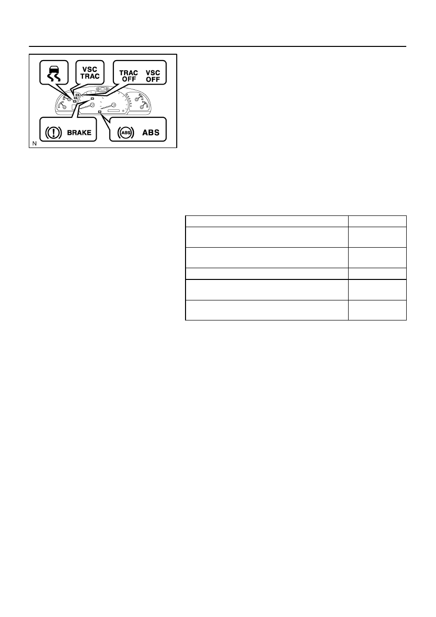
CHECK WARNING LIGHT
(a)
Release the parking brake pedal.
(b)
When the ignition switch is turned ON, check that the ABS
warning light, VSC TRAC warning light, VSC OFF (TRAC
OFF) indicator light, BRAKE warning light and SLIP indi-
cator light come on for approx. 3 seconds.
HINT:
When the parking brake is applied or the level of the brake
fluid is low, the BRAKE warning light comes on.
If the indicator check result is not normal, proceed to trou-
bleshooting for the ABS warning light circuit, VSC TRAC
warning light circuit, VSC OFF (TRAC OFF) indicator light
circuit, BRAKE warning light circuit or SLIP indicator light
circuit.
Trouble Area
See page
ABS warning light circuit
VSC TRAC warning light circuit
VSC OFF (TRAC OFF) indicator light circuit
BRAKE warning light circuit
SLIP indicator light circuit
The DTCs are simultaneously stored in the memory. The
DTCs can be read by connecting the SST between TC
and CG terminals of the DLC3 and observing the blinking
of the ABS and VSC warning lights, or by connecting a
hand–held tester.
This system has a sensor signal check function (TEST
MODE) (See page
The DTC can be read by connecting the SST between ter-
minals TS and CG of the DLC3 and observing the blinking
of the ABS and VSC TRAC warning lights, or by connect-
ing a hand–held tester.
Нет комментариевНе стесняйтесь поделиться с нами вашим ценным мнением.
Текст