Toyota Sequoia (2005). Manual — part 161
A23475
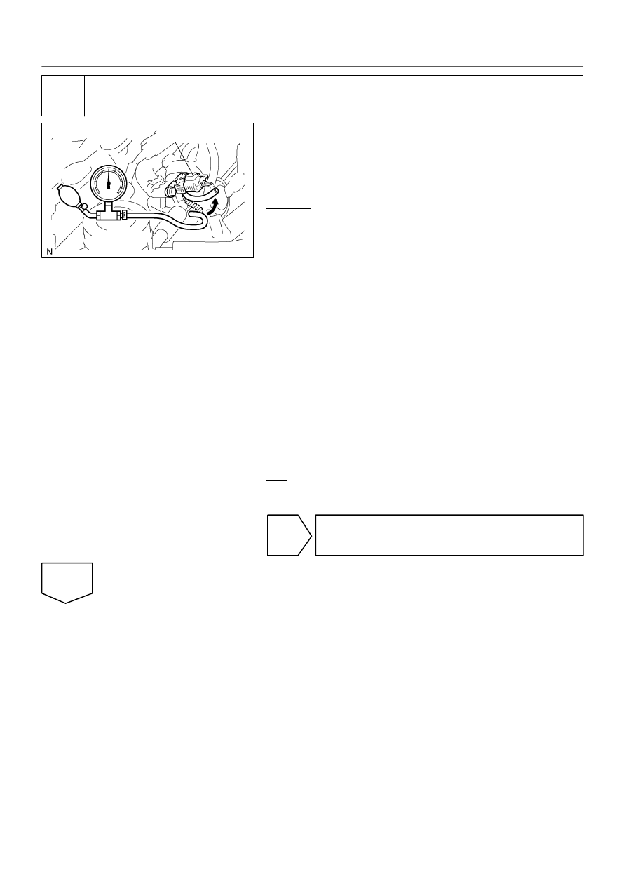
Pressure Gauge
Pressure Sensor
–
DIAGNOSTICS
ENGINE
DI–439
633
12
Check air pump operation.
PREPARATION:
(a)
Connect the pressure gauge to the air switching valve as
shown in the illustration.
(b)
Connect the hand–held tester to the DLC3.
(c)
Turn the ignition switch ON and turn the tester ON.
CHECK:
(a)
When the air pump is operated using the hand–held tes-
ter, measure the secondary air injection system pressure.
(b)
Select the following menu items: DIAGNOSIS/EN-
HANCED OBD II/ACTIVE TEST/AIR INJ CHECK/MANU-
AL OPERATION/OPERATION 3
HINT:
OPERATION 2: AP:ON, EASV:CLOSE, ASV1:CLOSE,
ASV2:CLOSE
NOTICE:
This test only allows technicians to operate the AI system
for 5 seconds. Furthermore, the test can be performed 4
times a trip. If the test is repeated, intervals of at least 30
seconds are required between tests.
While the AI system operation using the hand–held tester
is prohibited, the tester displays the prohibition (WAIT or
ERROR). If the ERROR (AI STATUS NG) is displayed on the
tester, stop the engine for 10 minutes and then try again..
OK:
Standard:
25 to 30 kPa or more
NG
Replace air pump.
OK

DI–440
–
DIAGNOSTICS
ENGINE
634
13
Check whether DTC output recurs.
PREPARATION:
(a)
Start the engine and warm it up.
(b)
Turn the ignition switch OFF.
(c)
Connect a hand–held tester to the DLC3.
(d)
Turn the ignition switch to ON and turn the tester ON.
(e)
Clear the DTCs (see page
(f)
Start the engine.
CHECK:
(a)
Perform SYSTEM CHECK to operate the air injection system.
Select the following menu items: DIAGNOSIS/ENHANCED OBD II/SYSTEM CHECK/AIR INJ
CHECK/AUTOMATIC OPERATION
(b)
After operating secondary air injection system, confirm the pending codes of the secondary air injec-
tion system by selecting the following menu items: DIAGNOSIS / ENHANCED OBD II / DTC INFO /
PENDING CODES.
(c)
Read DTC and check no DTC.
OK:
DTC P2444 or P2445 for the secondary air injection system is not output.
NG
Check for intermittent problems
(See page
OK
END
B17443
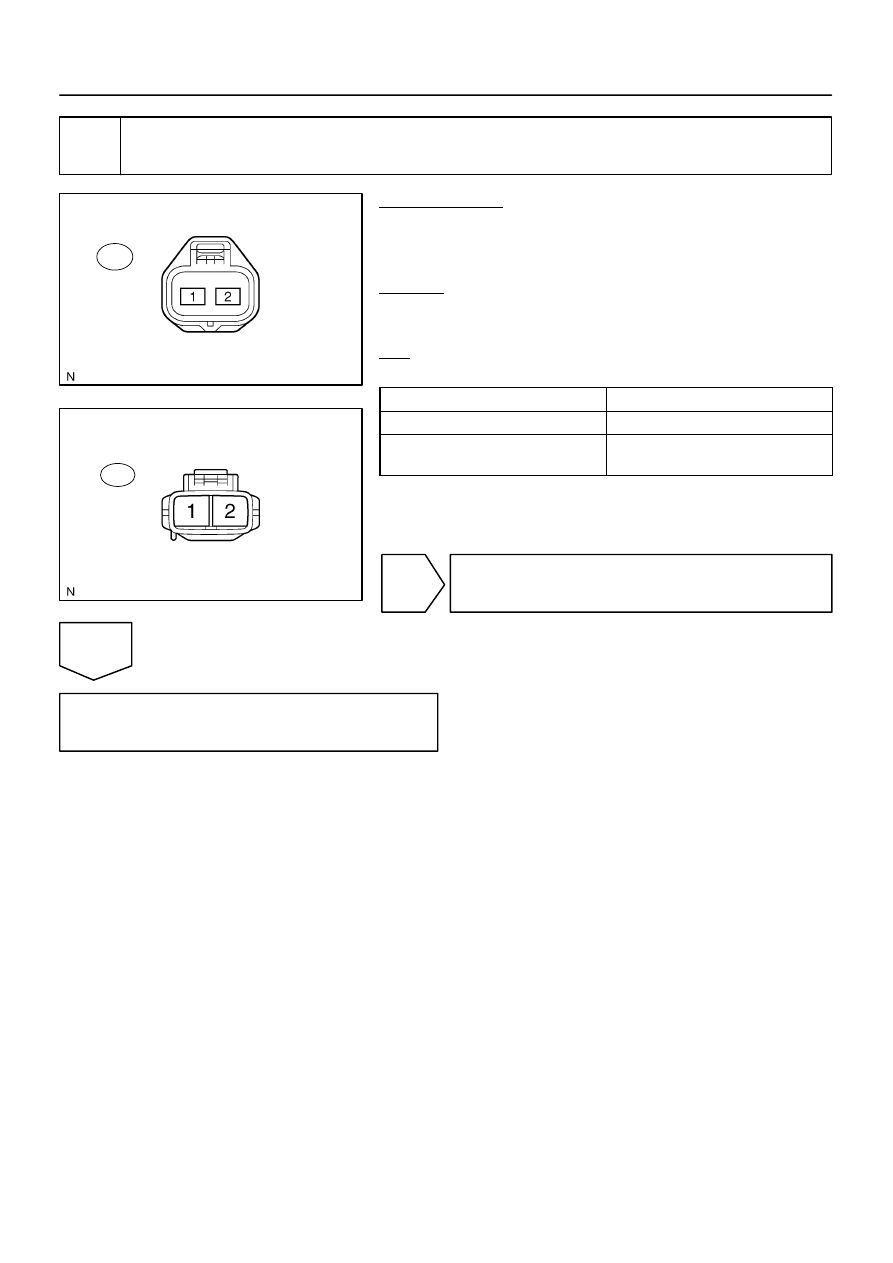
Wire Harness Side:
Air Injection Driver Connector
A40
B17438
Wire Harness Side:
Air Pump Connector
A43
–
DIAGNOSTICS
ENGINE
DI–441
635
14
Check for open and short in harness and connector between air injection driver
and air pump.
PREPARATION:
(a)
Remove the intake manifold (see page
).
(b)
Disconnect the A40 air injection driver connector.
(c)
Disconnect the A43 air pump connector.
CHECK:
Measure the resistance between the wire harness side connec-
tors.
OK:
Standard:
Tester Connection
Specified Condition
VP (A40–2) – A43–2
Below 1
Ω
VP (A40–2) or A43–2 –
Body ground
10 k
Ω
or higher
NG
Repair or replace harness or connector.
OK
Replace air injection driver.
A23667
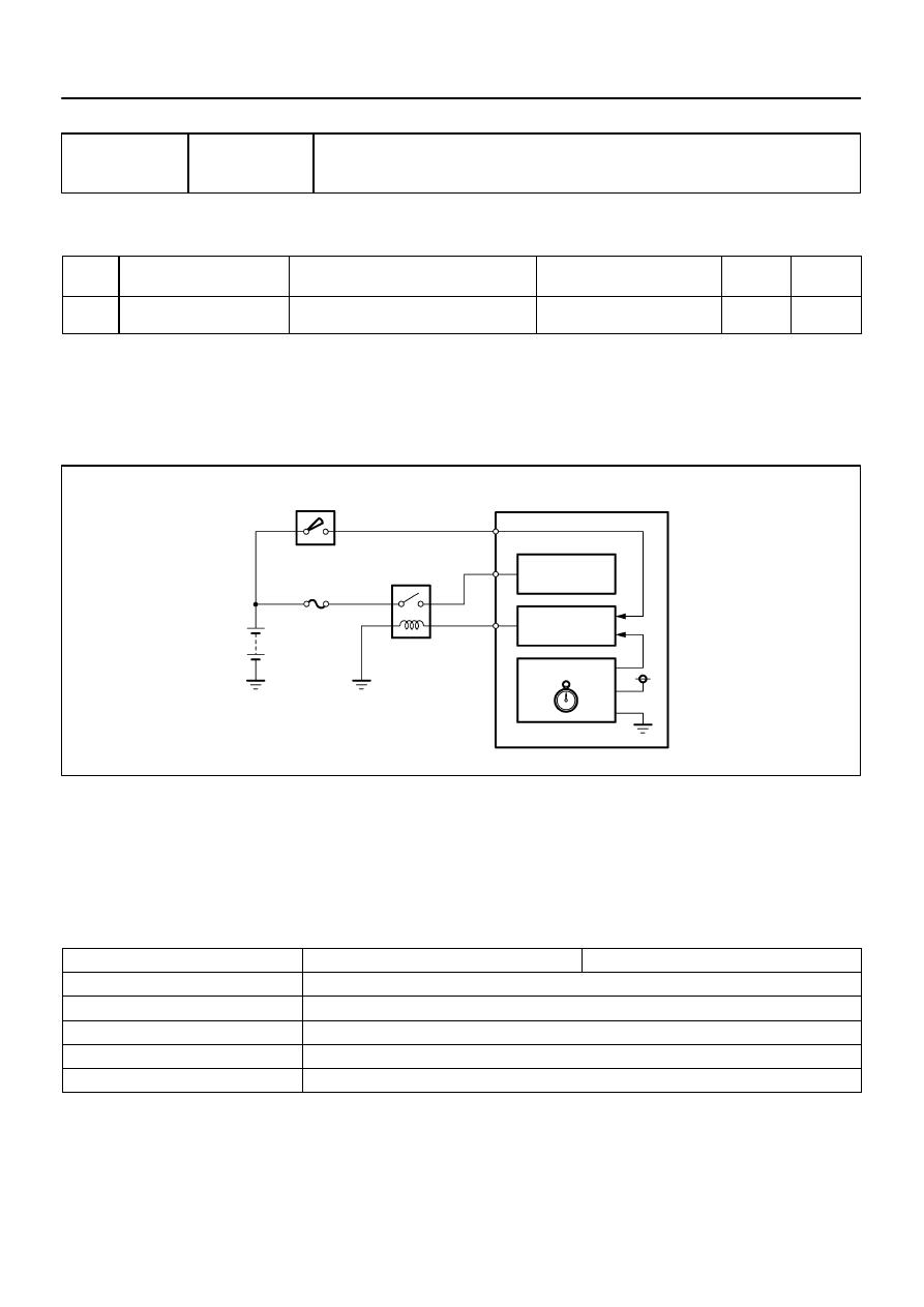
Soak Timer Circuit
Ignition Switch
IGSW
Power
ECM
EFI MAIN
MREL
+B
15 A
Source IC
Soak Timer IC
Main Relay
Control IC
Battery
DI–442
–
DIAGNOSTICS
ENGINE
636
DTC
P2610
ECM/PCM Internal Engine OFF Timer Perfor-
mance
DTC SUMMARY
DTC
Monitoring Items
Malfunction Detection Conditions
Trouble Areas
Detection
Timings
Detection
Logic
P2610
Soak timer (built into ECM)
ECM internal malfunction
ECM
Engine
running
2 trip
CIRCUIT DESCRIPTION
To ensure the accuracy of the EVAP (Evaporative Emission) monitor values, the soak timer, which is built
into the ECM, measures 5 hours (
15 minutes) from when the ignition switch is turned OFF, before the moni-
tor is run. This allows the fuel to cool down, which stabilizes the Fuel Tank Pressure (FTP). When 5 hours
have elapsed, the ECM turns on.
MONITOR DESCRIPTION
5 hours after the ignition switch is turned OFF, the soak timer activates the ECM to begin the EVAP system
monitor. While the engine is running, the ECM monitors the synchronization of the soak timer and the CPU
clock. If these two are not synchronized, the ECM interprets this as a malfunction, illuminates the MIL and
sets the DTC (2 trip detection logic).
MONITOR STRATEGY
Related DTCs
P2610
Soak timer (built into ECM)
Required sensors/components
ECM
Frequency of operation
Once per driving cycle
Duration
10 min.
MIL operation
2 driving cycles
Sequence of operation
None
DIDFX–01
Нет комментариевНе стесняйтесь поделиться с нами вашим ценным мнением.
Текст