Toyota Sequoia (2005). Manual — part 311
–
DIAGNOSTICS
ABS WITH EBD & BA & TRAC & VSC SYSTEM
DI–1039
1233
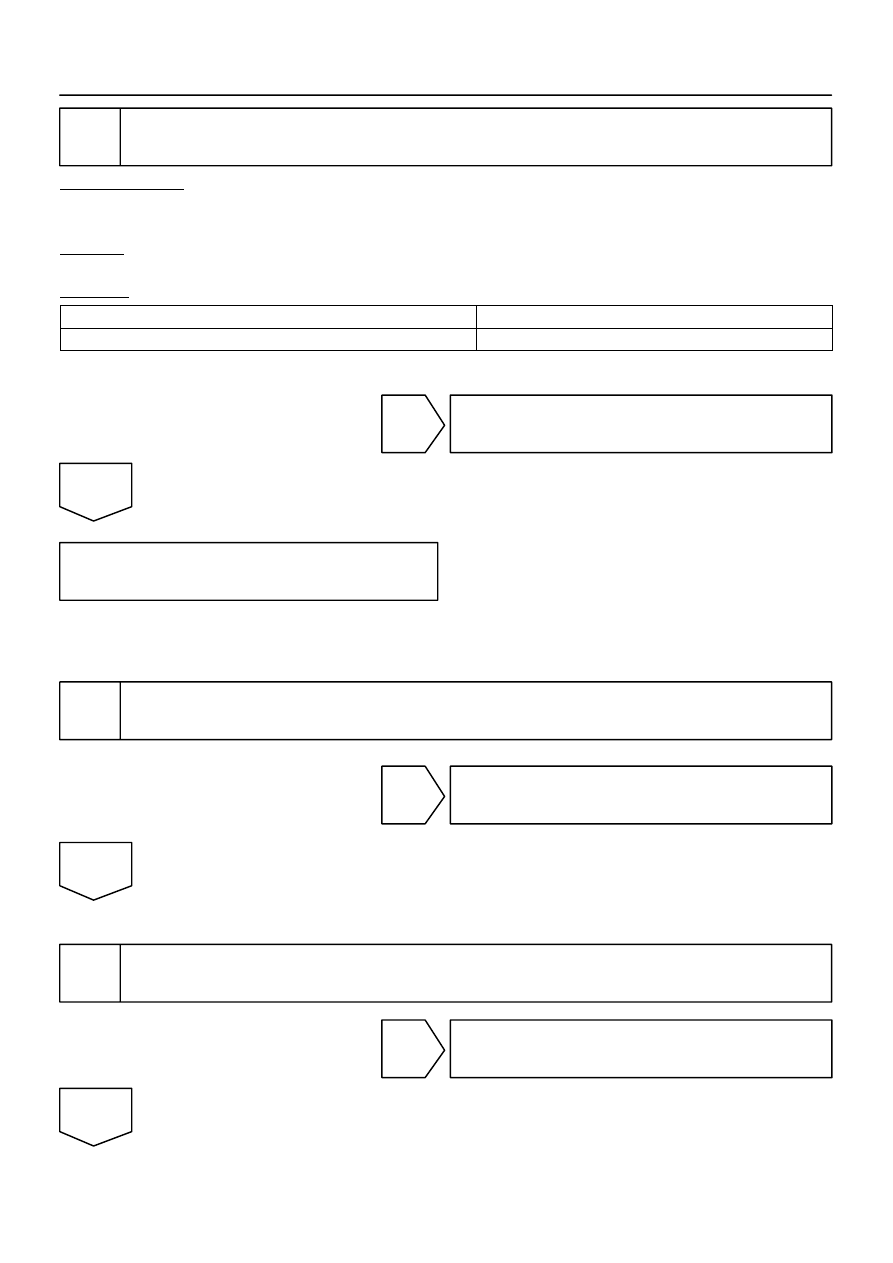
2
Replace the translate ECU and check whether or not the trouble occurs again.
PREPARATION:
(a)
Clear the DTC (See page
(b)
Turn the ignition switch OFF.
CHECK:
Turn the ignition switch to the ON position, and check if the same DTC still remains in the memory.
RESULT:
DTC is output
A
DTC is not output
B
B
END.
A
Check and replace skid control ECU
(See page
).
NOTICE:
When replacing the skid control ECU, perform the zero point calibration (See page
).
3
Check harness and connector between translate ECU and skid control ECU
(CAN1 circuit).
NG
Repair or replace parking brake switch circuit
(CAN1 circuit).
OK
4
Check harness and connector between translate ECU and combination meter
(See page
).
NG
Repair or replace harness or connector.
OK
DI–1040
–
DIAGNOSTICS
ABS WITH EBD & BA & TRAC & VSC SYSTEM
1234
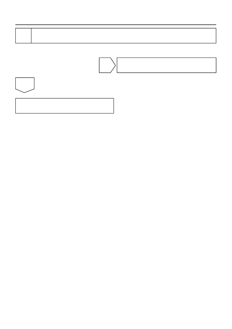
5
Check BRAKE warning light.
See combination meter troubleshooting on page
NG
Repair combination meter assembly
(See page
OK
Check and replace skid control ECU
(See page
).
NOTICE:
When replacing the skid control ECU, perform the zero point calibration (See page
).

–
DIAGNOSTICS
ABS WITH EBD & BA & TRAC & VSC SYSTEM
DI–1041
1235
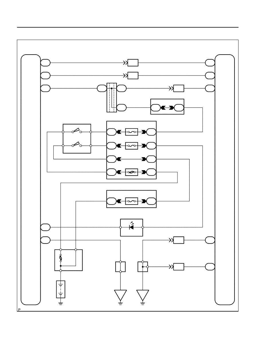
SLIP Indicator Light Circuit (Remains ON)
CIRCUIT DESCRIPTION
The SLIP indicator light blinks during VSC & TRAC operation.
The skid control ECU is connected to the translate ECU via the CAN communication system.
DI947–04
F19779
ABS & VSC Actuator
(Skid Control ECU)
IG1
13
S1
B–R
1
IL1
B–R
B–R
B–R
B–R
B–R
A
J38
A
J37
A
J37
1
T5
IG1
Translate ECU
8
3C
8
3A
J/C
4
1F
11
1H
7
1J
1
1L
4
1C
2
1C
3
1C
6
1C
ECU–IG
IGN1
AM1
1
2
Instrument Panel J/B
B–O
W–R
W
B–Y
B–R
W–R
W–L
W–L
IG1
IG2
AM1
AM2
I18
Ignition SW
W
W–R
W
B
Engine Room J/B
1
2C
1
2D
AM2
Combination Meter
1
C6
24
SLIP
W–R
W–R
O
J43
J/C
O
A
A
W
8
4
B
5
B
Battery
F10
Fusible
Link
Block
ALT
IG
IG
W–B
37
T5
40
T5
IND
GND
A
A
J18
J/C
W–B
W–B
W–B
17
IL1
1
S1
32
S1
9
IL1
GND1
GND2
2
6
1
5
Sub J/B No.3
O
B–O
7
IL2
6
IL2
11
T5
7
T5
2
S1
6
S1
VSC+
VSC–
L
W
L
W
CANH
CANL
(*) CAN1 Circuit
(*)
(*)
(*)
(*)
DI–1042
–
DIAGNOSTICS
ABS WITH EBD & BA & TRAC & VSC SYSTEM
1236
WIRING DIAGRAM
Нет комментариевНе стесняйтесь поделиться с нами вашим ценным мнением.
Текст