Toyota Sequoia (2005). Manual — part 10
Z17004
Fig. 1
OPEN
ECU
2
Sensor
2
2
2
1
1
1
1
A
B
C
Z17005
Fig. 2
ECU
Sensor
2
1
A
B
C
1
1
2
2
B04722
Fig. 3
ECU
Sensor
2
1
A
B1
C
1
1
2
2
1
2
B2
–
INTRODUCTION
HOW TO TROUBLESHOOT ECU CONTROLLED
SYSTEMS
IN–37
37
(d)
Prepare a test male terminal and insert it in the female ter-
minal, then pull it out.
NOTICE:
When testing a gold–plated female terminal, always use a
gold–plated male terminal.
HINT:
When the test terminal is pulled out more easily than others,
there may be poor contact in that section.
6.
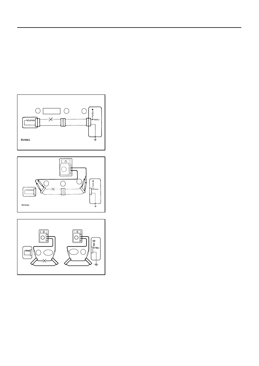
CHECK OPEN CIRCUIT
For an open circuit in the wire harness in Fig. 1, perform ”(a)
Continuity Check” or ”(b) Voltage Check” to locate the section.
(a)
Check the continuity.
(1)
Disconnect connectors ”A” and ”C” and measure
the resistance between them.
In the case of Fig. 2:
Between terminal 1 of connector ”A” and terminal 1
of connector ”C”
→
No continuity (open)
Between terminal 2 of connector ”A” and terminal 2
of connector ”C”
→
Continuity
Therefore, it is found out that there is an open circuit
between terminal 1 of connector ”A” and terminal 1
of connector ”C”.
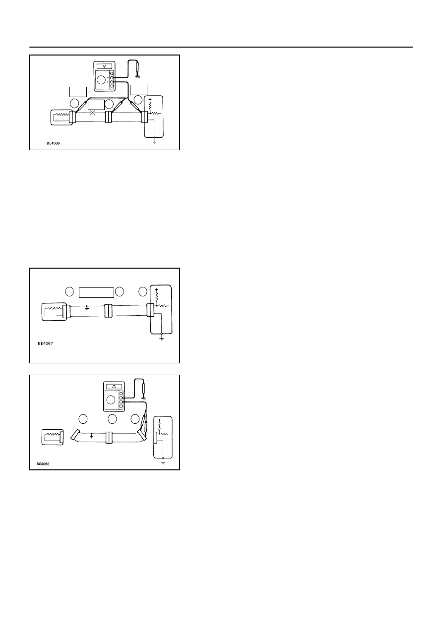
(2)
Disconnect connector ”B” and measure the resis-
tance between the connectors.
In the case of Fig. 3:
Between terminal 1 of connector ”A” and terminal 1
of connector ”B1”
→
Continuity
Between terminal 1 of connector ”B2” and terminal
1 of connector ”C”
→
No continuity (open)
Therefore, it is found out that there is an open circuit
between terminal 1 of connector ”B2” and terminal
1 of connector ”C”.
Z17007
Fig. 4
Sensor
2
1
A
C
1
1
2
2
B
5V
5V
5V
0V
Z17008
Fig. 5
2
1
A
C
1
1
2
2
B
SHORT
Z17009
Fig. 6
2
1
A
C
1
1
2
2
B
Sensor
ECU
IN–38
–
INTRODUCTION
HOW TO TROUBLESHOOT ECU CONTROLLED
SYSTEMS
38
(b)
Check the voltage.
In a circuit in which voltage is applied (to the ECU connec-
tor terminal), an open circuit can be checked by conduct-
ing a voltage check.
As shown in Fig. 4, with each connector still con-
nected, measure the voltage between body ground
and terminal 1 of connector ”A” at the ECU 5V out-
put terminal, terminal 1 of connector ”B”, and termi-
nal 1 of connector ”C”, in that order.
If the results are:
5V: Between Terminal 1 of connector ”A” and Body Ground
5V: Between Terminal 1 of connector ”B” and Body Ground
0V: Between Terminal 1 of connector ”C” and Body Ground
Then it is found out that there is an open circuit in the wire har-
ness between terminal 1 of ”B” and terminal 1 of ”C”.
7.
CHECK SHORT CIRCUIT
If the wire harness is shorted as in Fig. 5, locate the section by
conducting a ”continuity check with ground”.
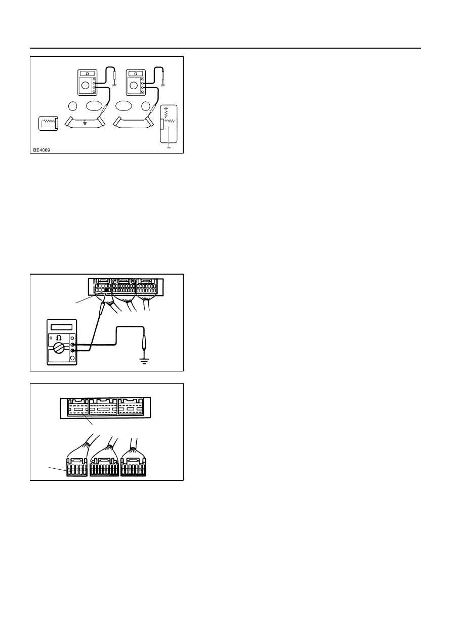
Check the continuity with ground.
(1)
Disconnect connectors ”A” and ”C” and measure
the resistance between terminals 1 and 2 of con-
nector ”A” and body ground.
In the case of Fig. 6:
Between terminal 1 of connector ”A” and body
ground
→
Continuity (short)
Between terminal 2 of connector ”A” and body
ground
→
No continuity
Therefore, it is found out that there is a short circuit
between terminal 1 of connector ”A” and terminal 1
of connector ”C”.
Z17808
Fig. 7
Sensor
2
1
A
B1
C
1
1
2
2
1
2
B2
ECU
IN0383
Example
Ground
IN0384
Ground
Ground
ECU Side
W/H Side
–
INTRODUCTION
HOW TO TROUBLESHOOT ECU CONTROLLED
SYSTEMS
IN–39
39
(2)
Disconnect connector ”B” and measure the resis-
tance between terminal 1 of connector ”A” and body
ground, and terminal 1 of connector ”B2” and body
ground.
In the case of Fig. 7:
Between terminal 1 of connector ”A” and body
ground
→
No continuity
Between terminal 1 of connector ”B2” and body
ground
→
Continuity (short)
Therefore, it is found out that there is a short circuit
between terminal 1 of connector ”B2” and terminal
1 of connector ”C”.
8.
CHECK AND REPLACE ECU
First check the ECU ground circuit. If it is faulty, repair it. If it is
normal, the ECU could be faulty, so replace the ECU with a nor-
mal functioning one and check that the symptoms appear.
(1)
Measure the resistance between the ECU ground
terminal and the body ground.
Resistance: 1
Ω
or less
(2)
Disconnect the ECU connector, check the ground
terminals on the ECU side and the wire harness
side for bend and check the contact pressure.

IN04Q–33
IN–40
–
INTRODUCTION
TERMS
40
TERMS
ABBREVIATIONS USED IN THIS MANUAL
Abbreviations
Meaning
ABS
Anti–Lock Brake System
A/C
Air Conditioner
AC
Alternating Current
ACC
Accessory
ACIS
Acoustic Control Induction System
ACM
Active Control Engine Mount
ACSD
Automatic Cold Start Device
A.D.D.
Automatic Disconnecting Differential
A/F
Air–Fuel Ratio
AHC
Active Height Control Suspension
ALR
Automatic Locking Retractor
ALT
Alternator
AMP
Amplifier
ANT
Antenna
APPROX.
Approximately
ASSY
Assembly
A/T, ATM
Automatic Transmission (Transaxle)
ATF
Automatic Transmission Fluid
AUTO
Automatic
AUX
Auxiliary
AVG
Average
AVS
Adaptive Variable Suspension
B+
Battery Voltage
BA
Brake Assist
BACS
Boost Altitude Compensation System
BAT
Battery
BDC
Bottom Dead Center
B/L
Bi–Level
B/S
Bore–Stroke Ratio
BTDC
Before Top Dead Center
BVSV
Bimetallic Vacuum Switching Valve
CB
Circuit Breaker
CCo
Catalytic Converter For Oxidation
CCV
Canister Closed Valve
CD
Compact Disc
CF
Cornering Force
CG
Center Of Gravity
CH
Channel
CKD
Complete Knock Down
COMB.
Combination
CPE
Coupe
CPS
Combustion Pressure Sensor
CPU
Central Processing Unit
CRS
Child Restraint System
CTR
Center
C/V
Check Valve
CV
Control Valve
CW
Curb Weight
Нет комментариевНе стесняйтесь поделиться с нами вашим ценным мнением.
Текст