Toyota Sequoia (2005). Manual — part 462
I28569
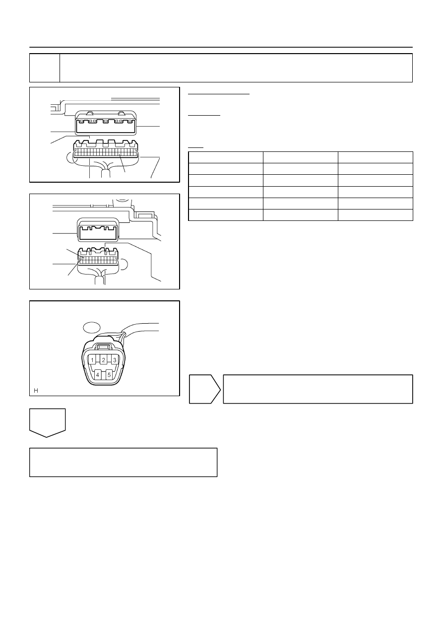
C5–26
Combination Meter:
I28570
C6–12
Combination Meter:
C6–11
I28575
Fuel Sender Gauge
Connector Front View:
F19
–
DIAGNOSTICS
COMBINATION METER SYSTEM
DI–1643
1837
4
Check harness and connector (Fuel sender gauge – combination meter).
PREPARATION:
Disconnect the combination meter connector.
CHECK:
Measure the resistance according to the value(s) in the table
below.
OK:
Tester connection
Condition
Specified condition
C5–26 – F19–2
Always
Below 1
Ω
C6–11 – F19–3
Always
Below 1
Ω
C6–12 – Body ground
Always
Below 1
Ω
C5–26 – Body ground
Always
10 k
Ω
or higher
C6–11 – Body ground
Always
10 k
Ω
or higher
NG
Repair or replace harness or connector.
OK
Replace combination meter
(See page
).
DI–1644
–
DIAGNOSTICS
COMBINATION METER SYSTEM
1838
Malfunction in engine coolant temperature receiver gauge
CIRCUIT DESCRIPTION
The ECM receives an engine coolant temperature signal from the engine coolant temperature sensor and
sends it to the A/C ECU.
The combination meter receives the signal from the A/C ECU through multiplex communication. Therefore,
if a malfunction occurs in the engine coolant temperature receiver gauge, there may be a malfunction in the
multiplex communication system, air conditioning system, or engine system.
(Multiplex communication system: See page
(Air conditioning system: See page
(Engine system: See page
INSPECTION PROCEDURE
1
Perform active test by hand–held tester.
PREPARATION:
(a)
Connect the hand–held tester to the DLC3.
(b)
Turn the ignition switch ON, and push the hand–held tester main switch ON.
CHECK:
From the display on the tester, perform the ”ACTIVE TEST”.
METER:
Item
Test Details
Diagnostic Note
COOLANT TEMP
HIGH / NORMAL / LOW (OFF)
Confirm that the vehicle is stopped and engine is
idling.
OK:
Engine coolant temperature receiver gauge readings change according to hand–held tester op-
eration.
OK
Go to engine system or air conditioning system
(See page
or
NG
Replace combination meter
(See page
).
DID92–01

–
DIAGNOSTICS
COMBINATION METER SYSTEM
DI–1645
1839
Operating light control rheostat does not change light brightness
CIRCUIT DESCRIPTION
Illumination intensity of the meter is increased by turning the knob of the light control rheostat switch clock-
wise, and it is decreased by turning the knob counterclockwise.
DID93–01
I28561
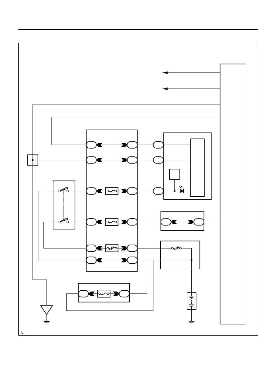
R6
Rheostat
To Each
Illumination Parts
To Each
Illumination Parts
Instrument Panel J/B
Combination Meter
I18
Ignition SW
J8
J/C
Sub J/B No. 3
F10
Fusible Link Block
Engine Room J/B
Battery
IE
T
ILL–
E
TR
IG
C5
C6
12
22
24
C6
Illumination
1F
1J
1C
1D
1H
1C
1C
8
2
11
9
3
4
13
6
IGN1
AM1
1H
1E
1C
4
1
1F
1L
6
7
5
6
1
2
2D
ECU–IG
2
1
8
8
3A
3E
8
4
5
1
3
4
5
6
ALT
AM2
IG2
AM2
1
1
2C
A
A
AM1
IG1
G
W–G
W–B
BR
W–G
W–G
W–B
W–G
B–R
B–Y
B–O
B–R
W
W–L
W–R
B–R
B
W–R
B
DI–1646
–
DIAGNOSTICS
COMBINATION METER SYSTEM
1840
WIRING DIAGRAM
Нет комментариевНе стесняйтесь поделиться с нами вашим ценным мнением.
Текст