Toyota Sequoia (2005). Manual — part 111
A23498
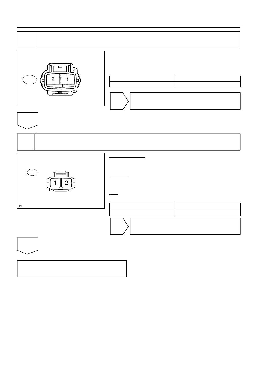
Component Side:
Air Pump Connector
Front View
A43
B17438
Wire Harness Side:
Air Pump Connector
A43
–
DIAGNOSTICS
ENGINE
DI–247
441
2
Check air pump resistance.
(a)
Remove the intake manifold (see page
).
(b)
Disconnect the air pump connector.
(c)
Measure the resistance of the air pump.
Standard:
Tester Connections
Specified Conditions
A43–1 – A43–2
0.4 to 1.0
Ω
NG
Replace air pump assembly.
OK
3
Check for open in harness and connector between air pump and body ground.
PREPARATION:
(a)
Remove the intake manifold (see page
).
(b)
Disconnect the A43 air pump connector.
CHECK:
Measure the resistance between the wire harness side connec-
tors and body ground.
OK:
Standard:
Tester Connection
Specified Condition
A43–1 – Body ground
Below 1
Ω
NG
Repair or replace harness or connector.
OK
Check for intermittent problems
(See page
B17443
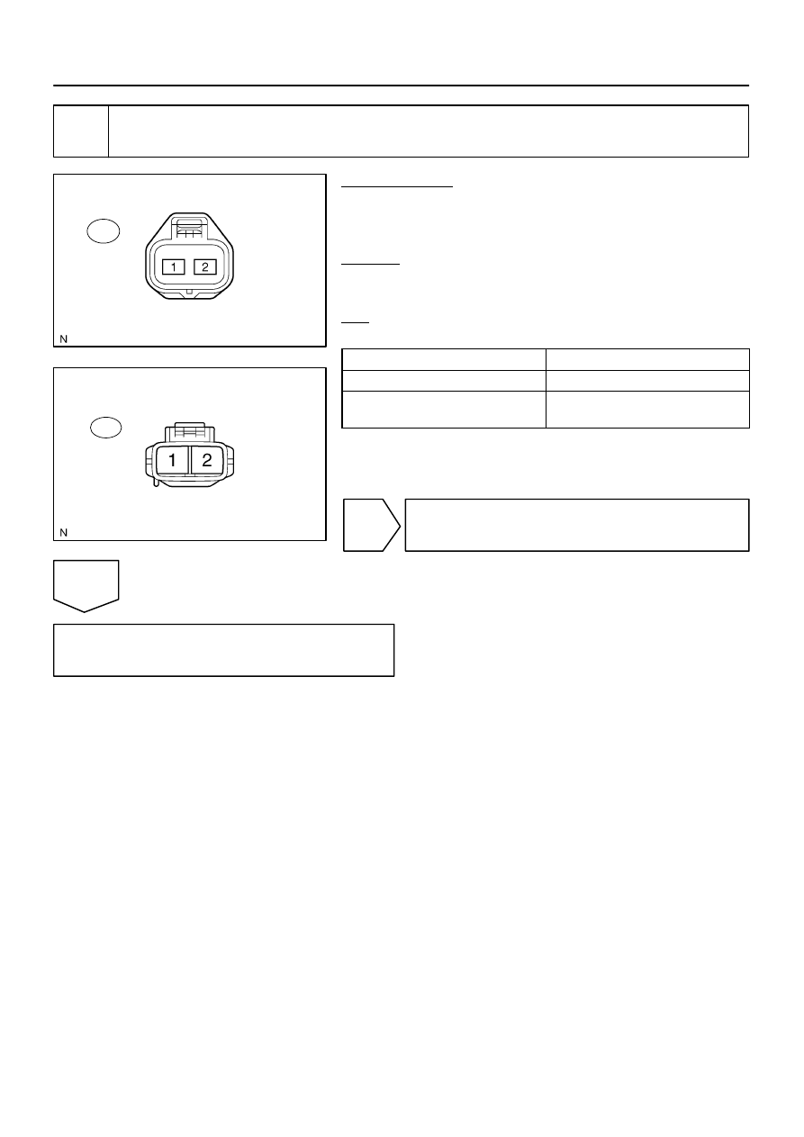
Wire Harness Side:
Air Injection Driver Connector
A40
B17438
Wire Harness Side:
Air Pump Connector
A43
DI–248
–
DIAGNOSTICS
ENGINE
442
4
Check for open and short in harness and connector between air injection driver
and air pump.
PREPARATION:
(a)
Remove the intake manifold (see page
).
(b)
Disconnect the A40 air injection driver connector.
(c)
Disconnect the A43 air pump connector.
CHECK:
Measure the resistance between the wire harness side connec-
tors.
OK:
Standard:
Tester Connection
Specified Condition
VP (A40–2) – A43–2
Below 1
Ω
VP (A40–2) or A43–2 –
Body ground
10 k
Ω
or higher
NG
Repair or replace harness or connector.
OK
Replace air injection driver.

–
DIAGNOSTICS
ENGINE
DI–249
443
DTC
P0420
Catalyst System Efficiency Below Threshold
(Bank 1)
DTC
P0430
Catalyst System Efficiency Below Threshold
(Bank 2)
MONITOR DESCRIPTION
The ECM uses the two sensors, mounted in front of and behind the Three–way Catalytic Converter (TWC),
to monitor its efficiency.
The first sensor, the Air–Fuel Ratio (A/F) sensor (sensor 1), sends pre–catalyst information to the ECM. The
second sensor, the Heated Oxygen (HO2) sensor (sensor 2), sends post–catalyst information to the ECM.
The ECM compares the information transmitted by these two sensors to determine the efficiency of the TWC
performance and its ability to store oxygen.
When the TWC is functioning properly, the variation in the oxygen concentration in the exhaust gas, after
it has passed through the TWC, is small. In this condition, the voltage output of sensor 2 slowly alternates
between the rich and lean signal voltages (shown in the illustration below). As the TWC performance efficien-
cy deteriorates, its oxygen storage capacity decreases, and the variation in the oxygen concentration in the
exhaust gas increases. As a result, the sensor voltage output fluctuates frequently.
While the catalyst monitor is running, the ECM measures the signal lengths of both sensors 1 and 2, and
calculates the ratio of the signal lengths to determine the extent of the TWC deterioration. If the deterioration
level exceeds the preset threshold, the ECM interprets this as the TWC malfunction. The ECM then illumi-
nates the MIL and sets the DTC.
DTC No.
DTC Detecting Condition
Trouble Area
P0420
P0430
OSC value smaller than standard value under active air–fuel
ratio control (2 trip detection logic)
Gas leakage on exhaust system
A/F sensor (Bank 1, 2 sensor 1)
Heated oxygen sensor (bank 1, 2 sensor 2)
Three–way catalytic converter
HINT:
Bank 1 refers to the bank that includes cylinder No.1.
Bank 2 refers to the bank that does not include cylinder No.1.
Sensor 1 refers to the sensor mounted in front of the Three–Way Catalytic Converter (TWC) and lo-
cated near the engine assembly.
Sensor 2 refers to the sensor mounted behind the TWC and located far from the engine assembly.
DID87–01

DI–250
–
DIAGNOSTICS
ENGINE
444
MONITOR STRATEGY
R l t d DTC
P0420
Bank 1 catalyst is deteriorated
Related DTCs
P0430
Bank 2 catalyst is deteriorated
Main sensors/components
Front and rear heated oxygen sensor
Required sensors/components
Related sensors/components
Mass air flow meter, Engine coolant temperature
sensor, Engine speed sensor, Intake air tempera-
ture sensor
Frequency of operation
Once per driving cycle
Duration
20 sec.
MIL operation
2 driving cycles
Sequence of operation
None
TYPICAL ENABLING CONDITIONS
It
Specification
Item
Minimum
Maximum
The monitor will run whenever these
DTCs are not present
See page
Battery voltage
11 V
–
Intake air temperature
–10
C (14
F)
–
Engine coolant temperature
75
°
C (167
°
F)
–
Atmospheric pressure coefficient
0.75
–
Idle
OFF
Engine RPM
–
3,200 rpm
A/F sensor
Activated
Fuel system status
Closed loop
Engine load
10 to 70 %
All of the following conditions are met
Condition 1, 2 and 3
1. MAF
6
to 75 g/sec
2. Front catalyst temperature (estimated)
620
to 830
C (1,148 to 1,526
F)
3. Rear catalyst temperature (estimated)
410 to 830
C (770 to 1,526
F)
Rear HO2S monitor
Completed
Shift position
4th
–
TYPICAL MALFUNCTION THRESHOLDS
Detection Criteria
Threshold
Oxygen storage capacity (OSC) of catalyst
Less than 0.16
Нет комментариевНе стесняйтесь поделиться с нами вашим ценным мнением.
Текст