Toyota Sequoia (2005). Manual — part 267
–
DIAGNOSTICS
TIRE PRESSURE WARNING SYSTEM
DI–863
1057
7
Check tire pressure warning lamp.
PREPARATION:
(a)
Turn the ignition switch to the ON position.
(b)
Enter TEST MODE (see page
(c)
Press the tire pressure warning reset switch for 1 second or more after switching to TEST MODE.
CHECK:
Does the tire pressure warning lamp come on while pressing the tire pressure warning reset switch?
RESULT:
Comes on
A
Does not come on
B
B
Go to step 14.
A
DI–864
–
DIAGNOSTICS
TIRE PRESSURE WARNING SYSTEM
1058
8
Check tire pressure warning lamp.
HINT:
Check all tires, including the spare, one at a time in this order: FR, FL, RR RL, Spare.
PREPARATION:
(a)
Turn the ignition switch to the ON position.
(b)
Rapidly reduce the pressure of the tires to approximately 120 kPa (1.2 kgf/cm
2
, 35 psi).
(c)
Check that the tire pressure warning lamp comes on for 1 second while rapidly reducing the pressure
or immediately after reducing the pressure.
(d)
Note the check results.
(e)
Set the tire pressure to the specified value.
CHECK:
Check that the tire pressure warning lamp comes on when each of the wheels is inspected.
RESULT:
Does not come on (All wheels)
A
Does not come on (Some wheels)
B
Comes on (All wheels)
C
B
Replace tire pressure monitor receiver assy
(See page
HINT:
Replace the tire pressure monitor valve sub–assy for which the
tire pressure warning lamp did not come on during inspection.
C
Perform initialization (See page
A
F19136
Tire Pressure Monitor ECU:
T17
RF5V
GND2
RDA
F19137
Tire Pressure Monitor Receiver Assy:
T19
+5V
GND
RDA
F19138
Tire Pressure Monitor ECU:
T17
RF5V
GND2
–
DIAGNOSTICS
TIRE PRESSURE WARNING SYSTEM
DI–865
1059
9
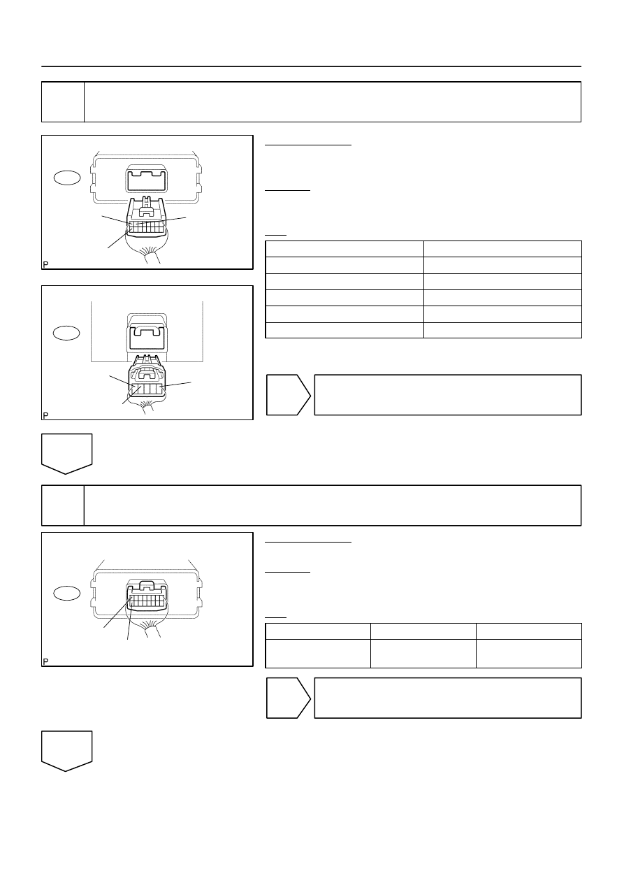
Check harness and connector (Tire pressure monitor receiver assy – Tire pres-
sure monitor ECU).
PREPARATION:
Disconnect the tire pressure monitor receiver assy T19 connec-
tor and tire pressure monitor ECU T17 connector.
CHECK:
Measure the resistance according to the value(s) in the table
below.
OK:
T17–7 (RDA) – T19–1 (RDA)
Below 1
Ω
T17–8 (RF5V) – T19–5 (+5V)
Below 1
Ω
T17–16 (GND2) – T19–4 (GND)
Below 1
Ω
T17–7 (RDA) – Body ground
10 k
Ω
or higher
T17–8 (RF5V) – Body ground
10 k
Ω
or higher
T17–16 (GND2) – Body ground
10 k
Ω
or higher
NG
Repair or replace harness or connector.
OK
10
Inspect tire pressure monitor ECU.
PREPARATION:
Connect the tire pressure monitor ECU T17 connector.
CHECK:
Measure the voltage according to the value(s) in the table be-
low.
OK:
Tester Connection
Condition
Specified Condition
T17–8 (RF5V) –
T17–16 (GND2)
Ignition Switch ON
4.5 to 5.5 V
NG
Check power source circuit
(See page
).
OK
DI–866
–
DIAGNOSTICS
TIRE PRESSURE WARNING SYSTEM
1060
11
Replace tire pressure monitor receiver assy (See page
NEXT
12
Check DTC (See page
PREPARATION:
Clear the DTCs.
CHECK:
Check for a DTC.
OK:
DTC is not output.
OK
End
NG
13
Replace tire pressure monitor ECU and check DTC.
PREPARATION:
(a)
Replace the tire pressure monitor ECU (see page
(b)
Clear the DTCs.
CHECK:
Check for a DTC.
OK:
DTC is not output.
NG
Replace tire pressure monitor valve sub–assy
(See page
OK
End
Нет комментариевНе стесняйтесь поделиться с нами вашим ценным мнением.
Текст