Toyota Sequoia (2005). Manual — part 57
A23544
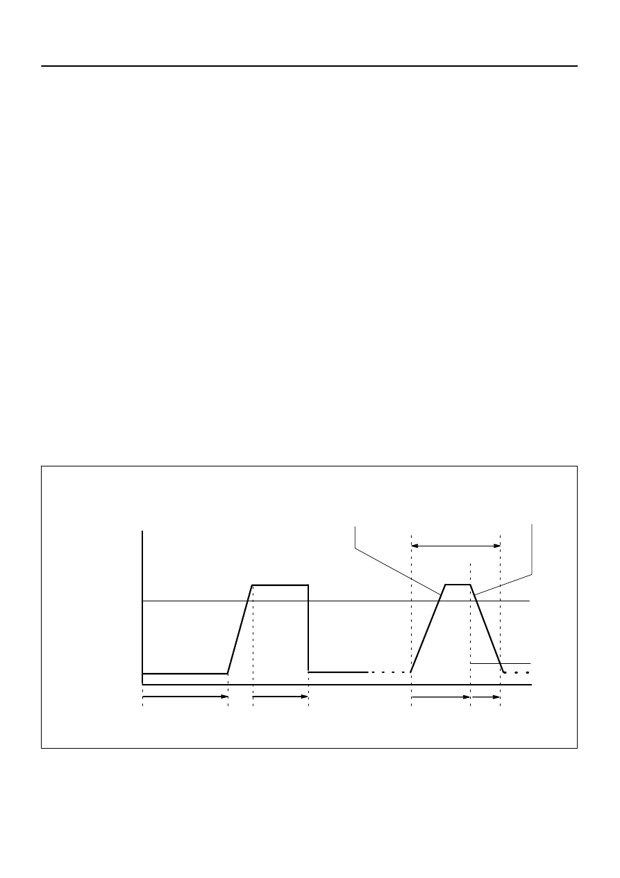
40 mph (64 km/h)
Idling
IG SW OFF
ECT:
75
C (167
F) or higher
Vehicle Speed
Warming up
(5)
(6)
10 minutes
or more
(7)
10 seconds
or more
4 seconds
or more
Time
At Least 3 times
(8)
(9)
(10)
Accelerator Pedal
Depressed
Accelerator Pedal
Released (Fuel–cut)
–
DIAGNOSTICS
ENGINE
DI–31
225
5.
AIR–FUEL RATIO (A/F) AND OXYGEN SENSOR (HO2) MONITOR (ACTIVE AIR–FUEL RATIO
CONTROL TYPE)
(a)
Preconditions
The monitor will not run unless:
2 minutes or more have elapsed since the engine was started.
The Engine Coolant Temperature (ECT) is 75
C (167
F) or higher.
Air–fuel ratio feedback control is performed.
Fuel–cut control is performed for 8 seconds or more.
(b)
Drive Pattern
(1)
Connect the hand–held tester to DLC3.
(2)
Turn the ignition switch to ON.
(3)
Clear DTCs (see page
(4)
Start the engine, and warm it up until the ECT reaches 75
C (167
F) or higher.
(5)
Drive the vehicle at 40 mph (64 km/h) or more for at least 10 minutes.
(6)
Change the transmission to 2nd gear.
(7)
Accelerate the vehicle to 30 mph (48 km/h) or more by depressing the accelerator pedal for at
least 10 seconds.
(8)
Soon after performing step (8) above, release the accelerator pedal for at least 4 seconds without
depressing the brake pedal, in order to execute fuel–cut control.
(9)
Stop the vehicle and allow the engine to idle for 10 seconds or more.
(10) Allow the vehicle to decelerate until the vehicle speed declines to less than 6 mph (10 km/h).
(11) Repeat steps from (8) through (10) above at least 3 times in one driving cycle.
(c)
Monitor Status
(1)
Check the Readiness Monitor status displayed on the tester.
(2)
If the status does not switch to COMPL (complete), make sure that the preconditions have been
met, and then perform steps from (5) through (11) in Drive Pattern above.
A18915
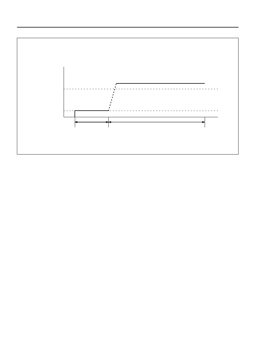
Idling
Ignition OFF
(40 km/h)
25 mph
Over 2 minutes
Over 500 seconds
DI–32
–
DIAGNOSTICS
ENGINE
226
6.
OXYGEN SENSOR HEATER MONITOR
(a)
Preconditions
The monitor will not run unless:
MIL is OFF
(b)
Drive Pattern
(1)
Connect the OBD II scan tool to the DLC3 to check monitor status and preconditions (refer to
(a)).
(2)
Start the engine and allow it to idle for 500 seconds or more.
(3)
Drive the vehicle at 25 mph (40 km/h) or more for at least 2 minutes.
(4)
Check the status of the readiness monitor on the scan tool display. If readiness status did not
switch to complete, ensure the preconditions are met, turn the ignition off and then repeat steps
(2) and (3).

DI3HJ–10
–
DIAGNOSTICS
ENGINE
DI–33
227
PROBLEM SYMPTOMS TABLE
Symptom
Suspect Area
See page
Engine does not crank (Does not start)
22.Starter
23.Starter relay
24.Park/neutral position switch
No initial combustion (Does not start)
1. ECM power source circuit
2. Fuel pump control circuit
3. Engine control module (ECM)
No complete combustion (Does not start)
1. Fuel pump control circuit
Engine cranks normally but difficult to start
1. Starter signal circuit
2. Fuel pump control circuit
3. Compression
Difficult to start with cold engine
1. Starter signal circuit
2. Fuel pump control circuit
Difficult to start with hot engine
1. Starter signal circuit
2. Fuel pump control circuit
High engine idle speed (Poor idling)
1. A/C switch circuit
2. ECM power source circuit
–
Low engine idle speed (Poor idling)
1. A/C switch circuit
2. Fuel pump control circuit
–
Rough idling (Poor idling)
1. Compression
2. Fuel pump control circuit
Hunting (Poor idling)
1. ECM power source circuit
2. Fuel pump control circuit
Hesitation/Poor acceleration (Poor driveability)
1. Fuel pump control circuit
2. A/T faulty
–
Surging (Poor driveability)
1. Fuel pump control circuit
Engine stalls soon after starting
1. Fuel pump control circuit
Engine stalls during A/C operation
1. A/C switch circuit
2. Engine control module (ECM)
–
Unable to refuel/Difficult to refuel
1. ORVR system
–
DIDFO–01
B17410
E5
E6
E7
E8
E4
DI–34
–
DIAGNOSTICS
ENGINE
228
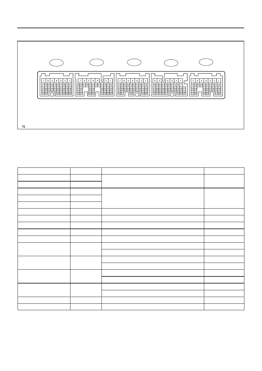
TERMINALS OF ECM
Each ECM terminals’ standard voltage is shown in the table below. In the table, first follow the information
under ”Condition”.
Look under ”Symbols (Terminals No.)” for the terminals to be inspected.
The standard voltage between the terminals is shown under ”STD Voltage”.
Use the illustration above as a reference for the ECM terminals.
Symbols (Terminals No.)
Wiring Color
Condition
STD Voltage
BATT (E4–3) – E1 (E6–1)
B–Y – BR
Al
9 t 14 V
+BM (E4–7) – E1 (E6–1)
W–G – BR
Always
9 to 14 V
IGSW (E4–9) – E1 (E6–1)
B–O – BR
+B (E4–1) – E1 (E6–1)
B–R – BR
IG switch ON
9 to 14 V
+B2 (E4–2) – E1 (E6–1)
B–R – BR
IG switch ON
9 to 14 V
MREL (E4–8) – E1 (E6–1)
B–W – BR
IG switch ON
9 to 14 V
VC (E8–23) – E2 (E8–28)
G–B – G–W
IG switch ON
4.5 to 5.5 V
VG (E8–30) – E2G (E8–29)
R–W – B–W
Idling, P or N position, A/C switch OFF
0.5 to 3.0 V
THA (E8–22) – E2 (E8–28)
Y–G – G–W
Idling, Intake air temp. 20
°
C (68
°
F)
0.5 to 3.4 V
THW (E8–21) – E2 (E8–28)
G–Y – G–W
Idling, Engine coolant temp. 80
°C (176°F)
0.2 to
1.0 V
VTA1 (E8 20)
E2 (E8 28)
B Y
G W
IG switch ON, Accelerator pedal released
0.5 to 1.2 V
VTA1 (E8–20) – E2 (E8–28)
B–Y – G–W
IG switch ON, Accelerator pedal depressed
3.2 to 4.8 V
VTA2 (E8 19)
E2 (E8 28)
P L
G W
IG switch ON, Accelerator pedal released
2.0 to 3.1 V
VTA2 (E8–19) – E2 (E8–28)
P–L – G–W
IG switch ON, Accelerator pedal depressed
4.7 to 5.1 V
VPA (E4 18)
E2 (E8 28)
G R
G W
IG switch ON, Accelerator pedal released
0.3 to 0.9 V
VPA (E4–18) – E2 (E8–28)
G–R – G–W
IG switch ON, Accelerator pedal depressed
3.2 to 4.8 V
VPA2 (E4 19)
E2 (E8 28)
L Y
G W
IG switch ON, Accelerator pedal released
1.8 to 2.7 V
VPA2 (E4–19) – E2 (E8–28)
L–Y – G–W
IG switch ON, Accelerator pedal depressed
4.7 to 5.1 V
VCPA (E4–26) – EPA (E4–20)
G–B – G–W
IG switch ON
4.5 to 5.5 V
VCP2 (E4–27) – EPA2 (E4–21)
L–R – L–B
IG switch ON
4.5 to 5.5 V
Нет комментариевНе стесняйтесь поделиться с нами вашим ценным мнением.
Текст