Toyota Sequoia (2005). Manual — part 754
SA3213
A
B
Front
C
D
R13228
R13229
FA0018
A B
Front
A
B
A: Inside
B: Outside
–
SUSPENSION AND AXLE
FRONT WHEEL ALIGNMENT
SA–9
3005
5.
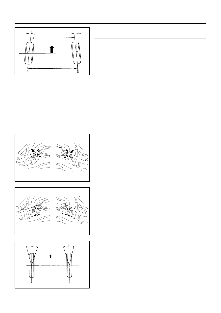
INSPECT TOE–IN
Toe–in (total):
UCK35L–GKBSKA
Tire size: P245/70R16
Tire size: P265/70R16 and P265/65R17
Tire size: P265/65R17 (*1)
UCK35L–GKBLKA
UCK45L–GKBSKA
Tire size: P265/70R16 (*1)
UCK45L–GKBLKA
A + B: 0
°05’ ±
0
°09’ (0.09° ± 0.15°)
C – D: 1.19
±
2 mm (0.05
±
0.08 in.)
A + B: 0
°05’ ±
0
°09’ (0.09° ± 0.15°)
C – D: 1.29
±
2 mm (0.05
±
0.08 in.)
A + B: 0
°05’ ±
0
°09’ (0.09° ± 0.15°)
C – D: 1.28
±
2 mm (0.05
±
0.08 in.)
A + B: 0
°05’ ±
0
°09’ (0.08° ± 0.15°)
C – D: 1.15
±
2 mm (0.05
±
0.08 in.)
A + B: 0
°05’ ±
0
°09’ (0.08° ± 0.15°)
C – D: 1.08
±
2 mm (0.04
±
0.08 in.)
A + B: 0
°05’ ±
0
°09’ (0.08° ± 0.15°)
C – D: 1.07
±
2 mm (0.04
±
0.08 in.)
A + B: 0
°04’ ±
0
°09’ (0.07° ± 0.15°)
C – D: 0.99
±
2 mm (0.04
±
0.08 in.)
(*1): Air suspension models only
If the toe–in is not within the specified values, adjust the rack
ends.
6.
ADJUST TOE–IN AND WHEEL ANGLE
(a)
Remove the 2 clips.
(b)
Loosen the tie rod end lock nuts.
(c)
Turn the right and left rack ends by an equal amount to
adjust the toe–in.
HINT:
Try to adjust the toe–in to the center of the specified values.
(d)
Make sure that the lengths of the right and left rack ends
are the same.
Rack end length difference: 1.5 mm (0.059 in.) or less
(e)
Tighten the tie rod end lock nuts.
Torque: 55 N·m (560 kgf·cm, 41 ft·lbf)
(f)
Place the boots on the seats and install the clips.
HINT:
Make sure that the boots are not twisted.
(g)
Inspect the wheel angle.
Turn the steering wheel fully and measure the turning
angle.

SA–10
–
SUSPENSION AND AXLE
FRONT WHEEL ALIGNMENT
3006
Wheel turning angle:
Model
Inside wheel
Outside wheel:
Reference
UCK35L–GKBSKA
–35
°24
’
(−35.40°)
32
°10
’ (32.16
°)
31
°54
’ (31.90
°) (*1)
UCK35L–GKBLKA
–35
°22’
(−35.36°)
32
°07
’ (32.12
°)
UCK45L–GKBSKA
–35
°37
’
(−35.61°)
32
°17
’ (32.28
°)
UCK45L–GKBLKA
–35
°35’
(−35.59°)
32
°16
’ (32.26
°)
(*1): Air suspension model with P265/65R17 tire only.
If the right and left wheel turning angles differ from the specified
values, readjust the toe–in and wheel angle to within the speci-
fied values. At this time, make sure that the lengths of the right
and left rack ends are the same.
Rack end length difference: 1.5 mm (0.059 in.) or less
SA2CO–01
–
SUSPENSION AND AXLE
WHEEL AND TIRE SYSTEM
SA–11
3007
WHEEL AND TIRE SYSTEM
PRECAUTION
1.
REMOVAL AND INSTALLATION OF TIRE PRESSURE MONITOR VALVE SUB–ASSY
(a)
When installing a tire, make sure that the tire pressure monitor valve does not interfere with the tire
bead in order to prevent damage to the sensor.
(b)
After completing the operation, remove the valve core to rapidly release air and check that the warning
light comes on. If not, the system may have a defect.
(c)
If there is air leakage, tighten the nut with a force of 4.0 N
⋅
m (41 kgf
⋅
cm, 35 in.
⋅
lbf) and push the valve
core 2 or 3 times to remove any dirt attached to the valve core.
If there is still air leakage, replace the grommet, the washer and the nut all together.
(d)
When installing the tire pressure monitor valve, check whether the rim, grommet, washer and nut are
clean. Use a manufacturer–specified cap.
(e)
When putting air into the tire, first install the tire pressure valve straight onto the stem of the tire pres-
sure monitor valve.
2.
TIRE AND WHEEL REPLACEMENT OR TIRE ROTATION
(a)
When replacing tires, be sure to check if the grommet of the tire valve is damaged. If so, replace the
grommet together with the washer and nut.
(b)
When tires and wheels are replaced, make sure to register the transmitter ID.
SA2CP–01
F16850
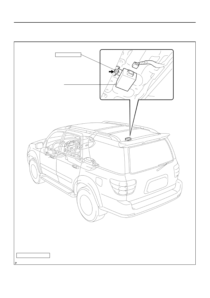
N·m (kgf·cm, ft·lbf)
: Specified torque
Tire Pressure Monitor
Receiver
7.5 (76, 66 in.·lbf)
SA–12
–
SUSPENSION AND AXLE
TIRE PRESSURE MONITOR RECEIVER
3008
TIRE PRESSURE MONITOR RECEIVER
COMPONENTS
Нет комментариевНе стесняйтесь поделиться с нами вашим ценным мнением.
Текст