Toyota Sequoia (2005). Manual — part 402
H41440
H23351
Spiral
Cable
Airbag
Sensor
Assembly
D2+
D2–
D Squib
(Dual stage –
2nd step)
B
C
E
D
F
A
Cowl Wire
A23
–
DIAGNOSTICS
SUPPLEMENTAL RESTRAINT SYSTEM
DI–1403
1597
21
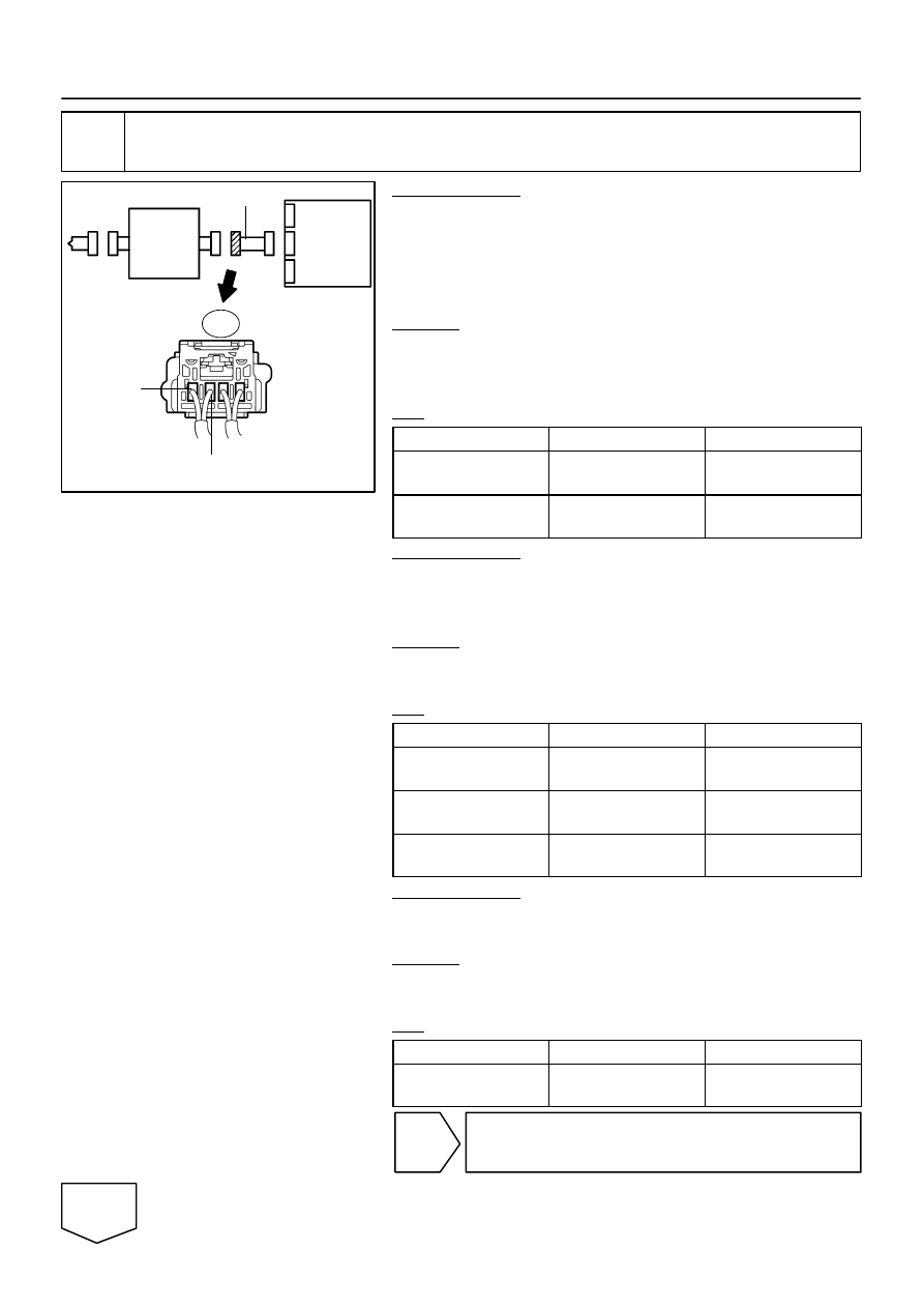
Check cowl wire.
PREPARATION:
(a)
Restore the released activation prevention mechanism of
connector ”B” to the original condition.
(b)
Disconnect the cowl wire connector from the spiral cable.
(c)
Connect the negative (–) terminal cable to the battery,
and wait for at least 2 seconds.
CHECK:
(a)
Turn the ignition switch to the ON position.
(b)
Measure the voltage according to the value(s) in the table
below.
OK:
Tester Connection
Condition
Specified Condition
A23–4 (D2+) –
Body ground
Ignition switch ON
Below 1 V
A23–3 (D2–) –
Body ground
Ignition switch ON
Below 1 V
PREPARATION:
(a)
Turn the ignition switch to the LOCK position.
(b)
Disconnect the negative (–) terminal cable from the bat-
tery, and wait for at least 90 seconds.
CHECK:
Measure the resistance according to the value(s) in the table
below.
OK:
Tester Connection
Condition
Specified Condition
A23–4 (D2+) –
A23–3 (D2–)
Always
Below 1
Ω
A23–4 (D2+) –
Body ground
Always
1 M
Ω
or higher
A23–3 (D2–) –
Body ground
Always
1 M
Ω
or higher
PREPARATION:
Release the activation prevention mechanism built into con-
nector ”B” (see page
CHECK:
Measure the resistance according to the value(s) in the table
below.
OK:
Tester Connection
Condition
Specified Condition
A23–4 (D2+) –
A23–3 (D2–)
Always
1 M
Ω
or higher
NG
Repair or replace cowl wire.
OK
H41479
H23350
Spiral
Cable
Airbag
Sensor
Assembly
D2+
D2–
D Squib
(Dual stage –
2nd step)
Color: Black
A
B
D
E
C
F
DI–1404
–
DIAGNOSTICS
SUPPLEMENTAL RESTRAINT SYSTEM
1598
22
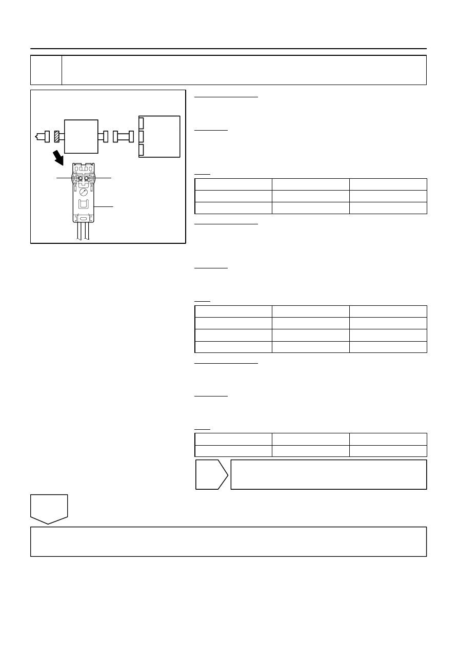
Check spiral cable.
PREPARATION:
Connect the negative (–) terminal cable to the battery, and wait
for at least 2 seconds.
CHECK:
(a)
Turn the ignition switch to the ON position.
(b)
Measure the voltage according to the value(s) in the table
below.
OK:
Tester Connection
Condition
Specified Condition
D2+ – Body ground
Ignition switch ON
Below 1 V
D2– – Body ground
Ignition switch ON
Below 1 V
PREPARATION:
(a)
Turn the ignition switch to the LOCK position.
(b)
Disconnect the negative (–) terminal cable from the bat-
tery, and wait for at least 90 seconds.
CHECK:
Measure the resistance according to the value(s) in the table
below.
OK:
Tester Connection
Condition
Specified Condition
D2+ – D2–
Always
Below 1
Ω
D2+ – Body ground
Always
1 M
Ω
or higher
D2– – body ground
Always
1 M
Ω
or higher
PREPARATION:
Release the activation prevention mechanism built into con-
nector ”D” (see page
CHECK:
Measure the resistance according to the value(s) in the table
below.
OK:
Tester Connection
Condition
Specified Condition
D2+ – D2–
Always
1 M
Ω
or higher
NG
Replace spiral cable (see page
OK
From the results of the above inspection, the malfunctioning part can now be considered normal.
To make sure of this, use the simulation method to check (see page
–
DIAGNOSTICS
SUPPLEMENTAL RESTRAINT SYSTEM
DI–1405
1599
HINT:
Perform the simulation method by selecting the check mode with the hand–held tester (see page
After selecting the check mode, perform the simulation method by wiggling each connector of the air-
bag system or driving the vehicle on a city or rough road (see page

DI–1406
–
DIAGNOSTICS
SUPPLEMENTAL RESTRAINT SYSTEM
1600
DTC
B1815/54 Short in P Squib (Dual stage – 2nd step)
Circuit
DTC
B1816/54 Open in P Squib (Dual stage – 2nd step)
Circuit
DTC
B1817/54 Short in P Squib (Dual stage – 2nd step)
Circuit (to Ground)
DTC
B1818/54 Short in P Squib (Dual stage – 2nd step)
Circuit (to B+)
CIRCUIT DESCRIPTION
The P squib (Dual stage – 2nd step) circuit consists of the airbag sensor assembly and the front passenger
airbag assembly.
The circuit instructs the SRS to deploy when deployment conditions are met.
These DTCs are recorded when a malfunction is detected in the P squib (Dual stage – 2nd step) circuit.
DTC No.
DTC Detection Condition
Trouble Area
B1815/54
The airbag sensor assembly receives a line short circuit
signal 5 times in the P squib (Dual stage – 2nd step) cir-
cuit during primary check.
P squib malfunction
Airbag sensor assembly malfunction
Front passenger airbag assembly (P squib, Dual stage – 2nd
step)
Airbag sensor assembly
Cowl wire
B1816/54
The airbag sensor assembly receives an open circuit sig-
nal in the P squib (Dual stage – 2nd step) circuit for 2 se-
conds.
P squib malfunction
Airbag sensor assembly malfunction
Front passenger airbag assembly (P squib, Dual stage – 2nd
step)
Airbag sensor assembly
Cowl wire
B1817/54
The airbag sensor assembly receives a short circuit to
ground signal in the P squib (Dual stage – 2nd step) circuit
for 0.5 seconds.
P squib malfunction
Airbag sensor assembly malfunction
Front passenger airbag assembly (P squib, Dual stage – 2nd
step)
Airbag sensor assembly
Cowl wire
B1818/54
The airbag sensor assembly receives a short to B+ circuit
signal in the P squib (Dual stage – 2nd step) circuit for 0.5
seconds.
P squib malfunction
Airbag sensor assembly malfunction
Front passenger airbag assembly (P squib, Dual stage – 2nd
step)
Airbag sensor assembly
Cowl wire
DIDHL–01
Нет комментариевНе стесняйтесь поделиться с нами вашим ценным мнением.
Текст