Toyota Sequoia (2005). Manual — part 599
DIDC5–01
I28205
I28206
Upper Left
Lower Left
I28207
–
DIAGNOSTICS
NAVIGATION SYSTEM
DI–2191
2385
DIAGNOSIS SYSTEM
HINT:
Illustrations may differ from the actual vehicle depending on the device settings and options. There-
fore, some detailed areas may not be shown exactly the same as on the actual vehicle.
After the ignition switch is turned on, check that the map is displayed before starting the diagnostic
mode. Otherwise, some items cannot be checked.
1.
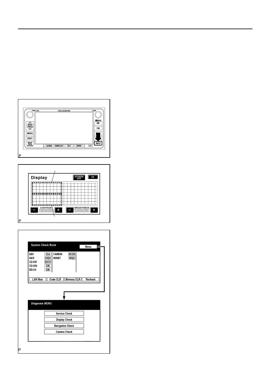
There are 2 methods to start diagnostic mode. Start the mode by using one of them.
2.
Method 1
(a)
Start the engine.
(b)
While pressing and holding ”INFO” switch, operate the
light control switch, OFF
→
TAIL
→
OFF
→
TAIL
→
OFF
→
TAIL
→
OFF.
(c)
The diagnostic mode starts and the service check screen
(”System Check Mode”) will be displayed. Service inspec-
tion starts automatically and the result will be displayed.
3.
Method 2
(a)
Start the engine.
(b)
Switch to the ”Display quality adjustment” screen.
(c)
From the display quality adjustment screen, touch the
corners of the screen in the following order: upper left
→
lower left
→
upper left
→
lower left
→
upper left
→
lower
left.
(d)
The diagnostic mode starts and ”Service Check” screen
will be displayed. Service inspection starts automatically
and the result will be displayed.
4.
Diagnosis MENU
(a)
Diagnostic screen will be displayed by pressing the menu
switch on the service check screen.
I28236
*1
*2
*3
*4
*1
*2
DI–2192
–
DIAGNOSTICS
NAVIGATION SYSTEM
2386
5.
DIAGNOSIS DISPLAY DETAILED DESCRIPTION
HINT:
This section contains a detailed description of displays within diagnostic mode.
Illustrations may differ from the actual vehicle depending on the device settings and options. There-
fore, some detailed areas may not be shown exactly the same as on the actual vehicle.
(a)
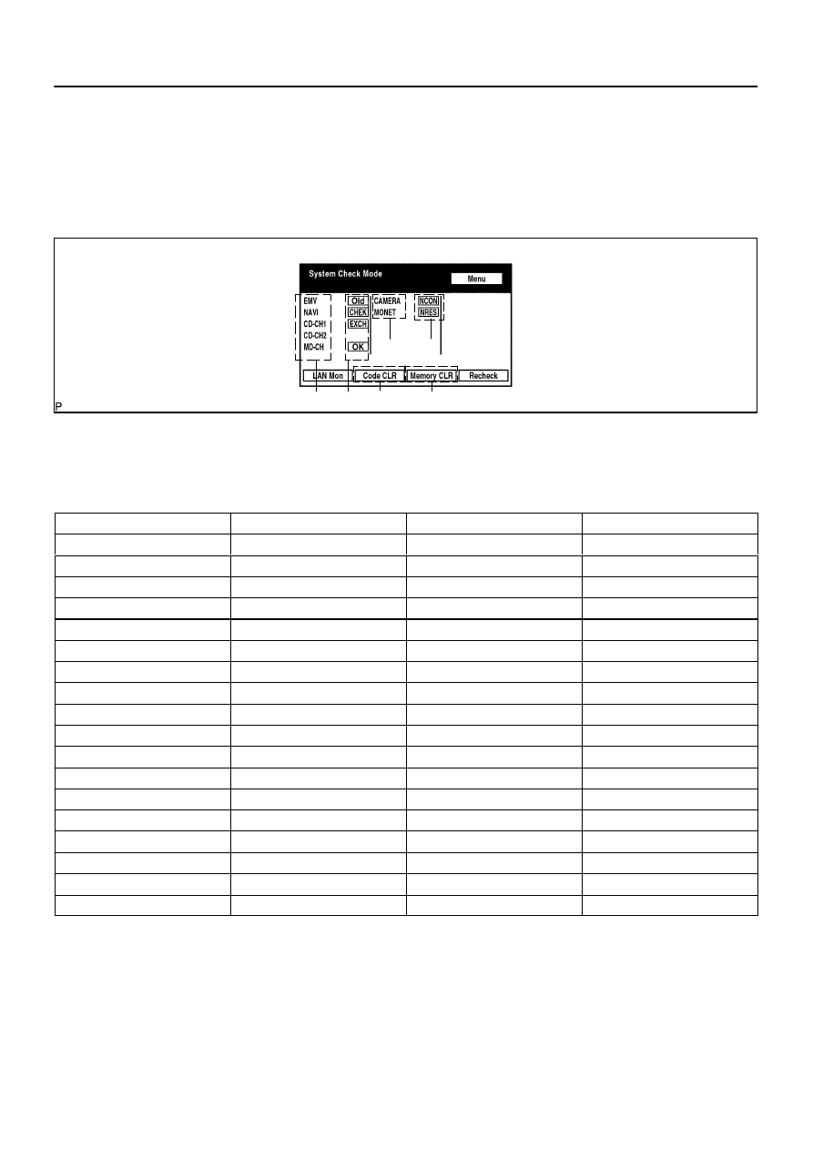
System Checks
(1)
System Check Mode Screen
Device Names and Hardware Address/*1
HINT:
Registered device names are displayed.
If a device name is unknown to the system, its physical address is shown instead.
Address No.
Name
Address No.
Name
110
EMV
120
AVX
128
1DIN TV
140
AVN
144
G–BOOK
178
NAVI
17C
MONET
190
AUDIO H/U
1AC
CAMERA–C
1B0
Rr–TV
1C0
Rr–CONT
1C2
TV–TUNER2
1C4
PANEL
1C6
G/W
1C8
FM–M–LCD
1D8
CONT–SW
1EC
BODY
1F0
RADIO TUNER
1F1
XM
1F2
SIRIUS
230
TV–TUNER
240
CD–CH2
250
DVD–CH
280
CAMERA
360
CD–CH1
3A0
MD–CH
17D
TEL
440
DSP–AMP
530
ETC
5C8
MAYDAY
1A0
DVD–P
1D6
CLOCK
1F4
RSA
1F6
RSE
480
AMP
–
–
I28237
–
DIAGNOSTICS
NAVIGATION SYSTEM
DI–2193
2387
Check Result/*2
HINT:
Result codes for all devices are displayed.
Result
Meaning
Action
OK
The device did not respond with a DTC (excluding commu-
nication DTCs from the AVC–LAN).
–
EXCH
The device responds with a ”replace”–type DTC.
Look up the DTC in ”Unit Check Mode” and replace the de-
vice.
CHEK
The device responds with a ”check”–type DTC.
Look up the DTC in Unit Check Mode”.
NCON
The device was previously present, but does not respond in
diagnostic mode.
1. Check power supply wire harness of the device.
2. Check the AVC–LAN of the device.
Old
The device responds with an ”old”–type DTC.
Look up the DTC in ”Unit Check Mode”.
NRES
The device responds in diagnostic mode, but gives no DTC
information.
1. Check power supply wire harness of the device.
2. Check the AVC–LAN of the device.
Code Clear/*3
Present DTCs are cleared.
Memory Clear/*4
Present and past DTCs and registered connected device names are cleared.
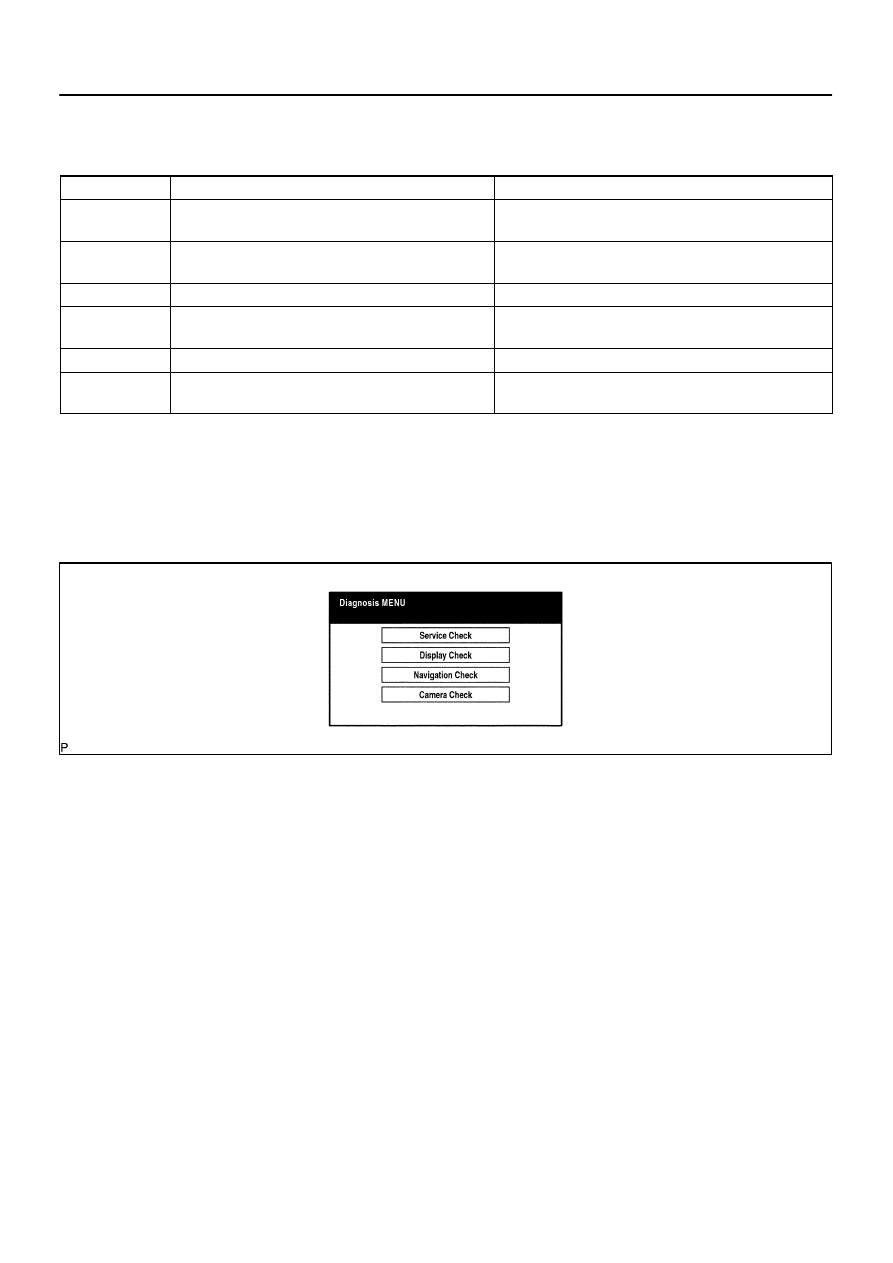
(1)
Diagnosis MENU Screen
HINT:
Each item is grayed out or not displayed based on the device settings.
I28238
*1
*2 *3
*5
*4
*6
I28239
*1
DI–2194
–
DIAGNOSTICS
NAVIGATION SYSTEM
2388
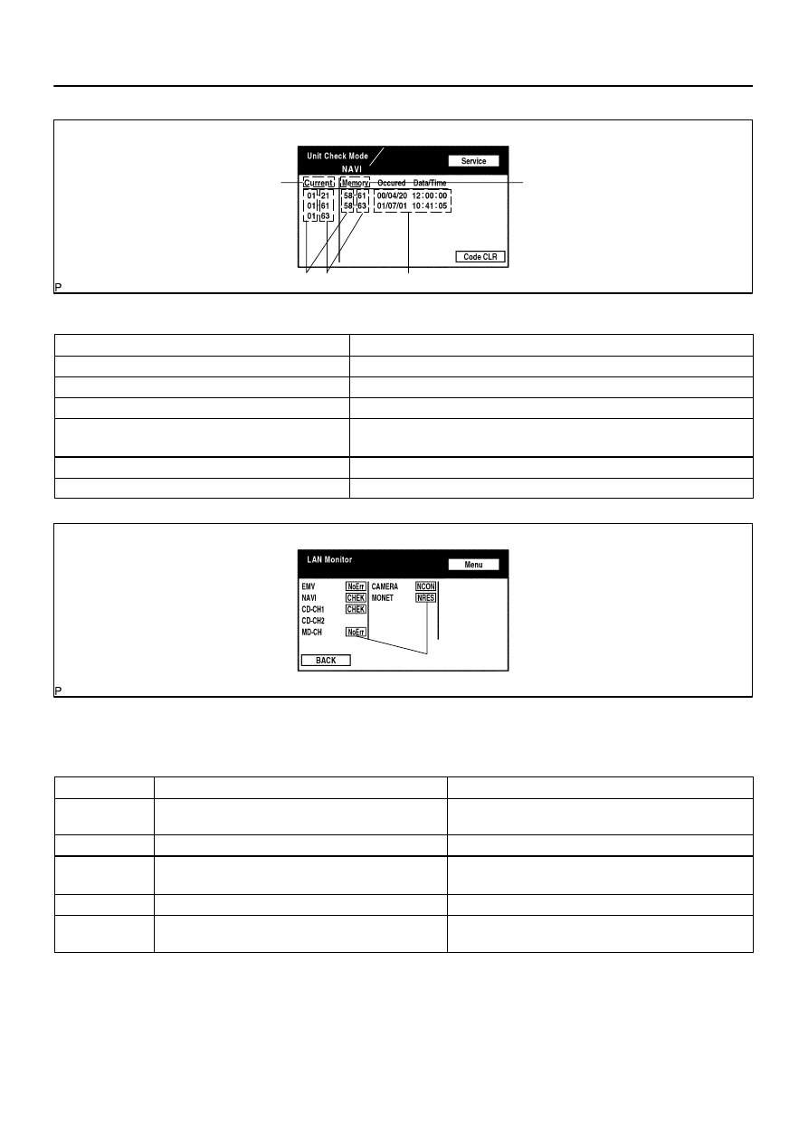
(2)
Unit Check Mode Screen
Screen Description
Display
Contents
Device name/*1
Target device
Segment/*2
Target device logical address
DTC/*3
DTC (Diagnostic Trouble Code)
Timestamp/*4
The time and date of past DTCs are displayed (The year is displayed in 2 digit
format.).
Present Code/*5
The DTC output at the service check is displayed.
Past Code/*6
Diagnostic memory results and recorded DTCs are displayed.
(3)
LAN Monitor (Original) Screen
Check Result/*1
HINT:
Check results of all the devices are displayed.
Result
Meaning
Action
No Err
(OK)
There are no communication DTCs.
–
CHEK
The device responds with a ”check”–type DTC.
Look up the DTC in ”Unit Check Mode”.
NCON
The device was previously present, but does not respond in
diagnostic mode.
1. Check power supply wire harness of the device.
2. Check the AVC–LAN of the device.
Old
The device responded with an old–type DTC.
Look up the DTC in ”Unit Check Mode”.
NRES
Device responds in diagnostic mode, but gives no DTC
information.
1. Check power supply wire harness of the device.
2. Check the AVC–LAN of the device.
Нет комментариевНе стесняйтесь поделиться с нами вашим ценным мнением.
Текст