Toyota Sequoia (2005). Manual — part 181
DIDIK–01
D13871
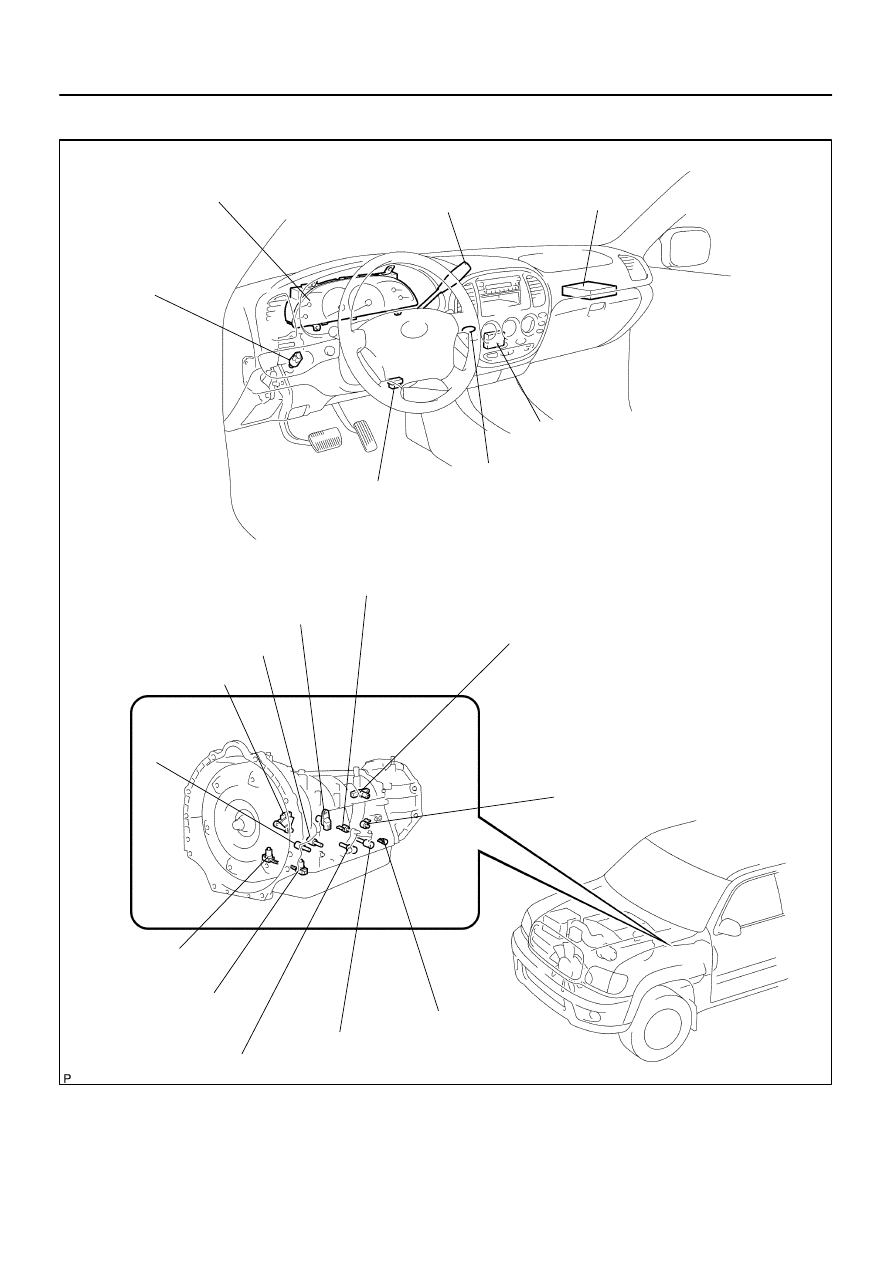
Combination Meter
DLC3
Stop Light Switch
ECM
Park/Neutral Position Switch
Speed Sensor (SP2)
Shift Solenoid Valve S1
Shift Solenoid Valve SR
Shift Solenoid Valve SLU
Shift Solenoid Valve SL2
ATF Temperature
Sensor No. 2
Integration Control and Panel
(Shift Position L Switch)
MIL
Shift Solenoid Valve SL1
Shift Solenoid
Valve SLT
ATF Temperature
Sensor No.1
Shift Solenoid Valve S2
Speed Sensor (NT)
AT Oil Temp Warning Light
Shift Lever
(O/D Main Switch)
4WD:
4WD Control ECU
–
DIAGNOSTICS
AUTOMATIC TRANSMISSION
DI–519
713
LOCATION
DIDIL–01
D14205
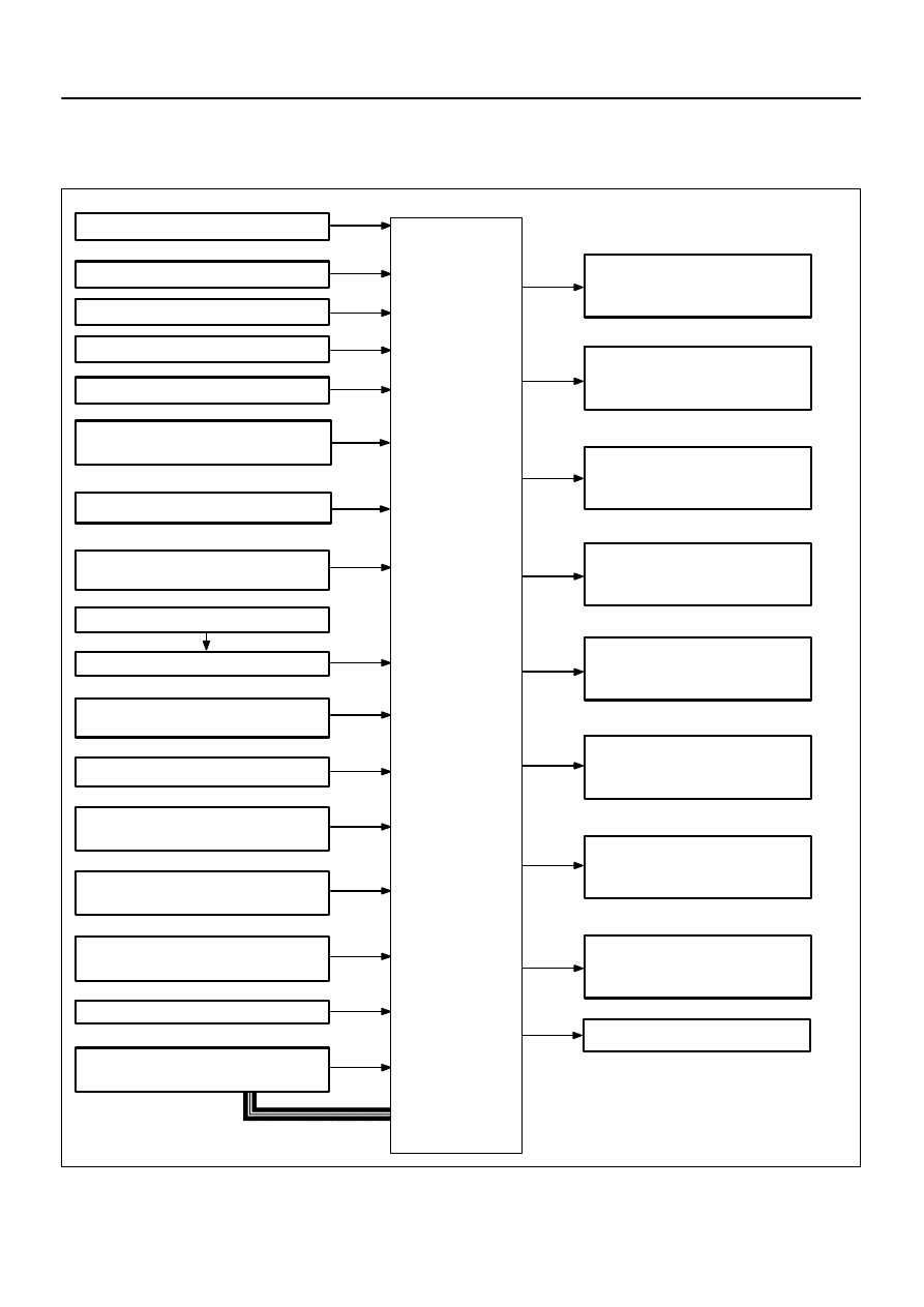
Shift Solenoid Valve S1
MIL
(Malfunction Indicator Lamp)
S1
S2
SL1
SL2
SLT
SLU
SR
W
Shift Solenoid Valve S2
Shift Solenoid Valve SL1
Shift Solenoid Valve SL2
Shift Solenoid Valve SLT
Shift Solenoid Valve SLU
Shift Solenoid Valve SR
OILW
AT Oil Temp Warning Light
ECM
Crankshaft Position Sensor
Engine CoolantTemperature Sensor
Combination Meter
Stop Lamp Switch Assy
DLC3
(Data Link Connector 3)
THW
VTA1, 2
VC
SPD
STP
TH01
TC
Throttle Position Sensor
ATF (Automatic Transmission
Fluid) Temperature Sensor No. 1
Mass Air Flow Meter
Accelerator Pedal Position Sensor
VPA
VPA2
Shift Lever
(O/D Main Switch)
Input Speed Sensor (NT)
NT
Output Speed Sensor (SP2)
SP2
TH02
ATF (Automatic Transmission
Fluid) Temperature Sensor No. 2
Skid Control ECU
NSW
Park/Neutral Position Switch
R, D, 3, 2
VG
NE
L
ODMS
Integration Control and Panel
(Shift Position L Switch)
L4
: 4WD
4WD Control ECU
CAN
DI–520
–
DIAGNOSTICS
AUTOMATIC TRANSMISSION
714
SYSTEM DIAGRAM
The configuration of the electronic control system in the A750E/A750F automatic transmission is as shown
in the following chart.
DIDIM–01
–
DIAGNOSTICS
AUTOMATIC TRANSMISSION
DI–521
715
SYSTEM DESCRIPTION
SYSTEM DESCRIPTION
The ECT (Electronic controlled automatic transmission) is an automatic transmission that electronically con-
trols shift timing using the ECM. The ECM detects electrical signals that indicate engine and driving condi-
tions, and controls the shift point, based on driver habits and road conditions. As a result, fuel efficiency and
power transmission performance are improved.
Shift shock has been reduced by controlling the engine and transmission simultaneously.
In addition, the ECT has features such as follows:
Diagnostic function.
Fail–safe function when a malfunction occurs.
DIDIN–01
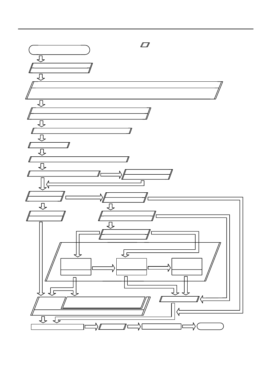
Vehicle Brought to Workshop
Customer Problem Analysis
Check DTC and Freeze Frame Data (Precheck)
Record or Print DTC and Freeze Frame Data
Clear DTC and Freeze Frame Data
Visual Inspection
Setting the Check Mode Diagnosis
1
Items inside
are titles of pages in this manual, with the
page number indicated in the bottom portion. See the indicated
pages for detailed explanations.
Connect a hand–held tester to DLC3.
If the display shows ”UNABLE TO CONNECT TO VEHICLE” when you have connected the
scan tool/hand–held tester, inspect DLC3
2
3
4
5
6
Symptom does not occur
Problem Symptom Confirmation
8
7
Symptom Simulation
P.
Symptom occurs
DTC Check
OK Code
11
Preliminary Check
DTC Chart
Mechanical System Test
Manual Shifting Test
OK
OK
Chapter 1
(Electronic)
Chapter 2
(On–Vehicle)
OK
Chapter 3
(Off–Vehicle)
OK
Matrix Chart of Problem Symptoms –
Circuit
Inspection
NG
Parts Inspection
NG
NG
NG
Identification of Problem
Repair
Confirmation Test
End
NG
NG
12
OK
13
14
15
16
17
9
10
18
O/D Main Switch Circuit Check
Shift Position L Switch Circuit Check
DI–522
–
DIAGNOSTICS
AUTOMATIC TRANSMISSION
716
HOW TO PROCEED WITH TROUBLESHOOTING
Нет комментариевНе стесняйтесь поделиться с нами вашим ценным мнением.
Текст