Toyota Sequoia (2005). Manual — part 722
B17496
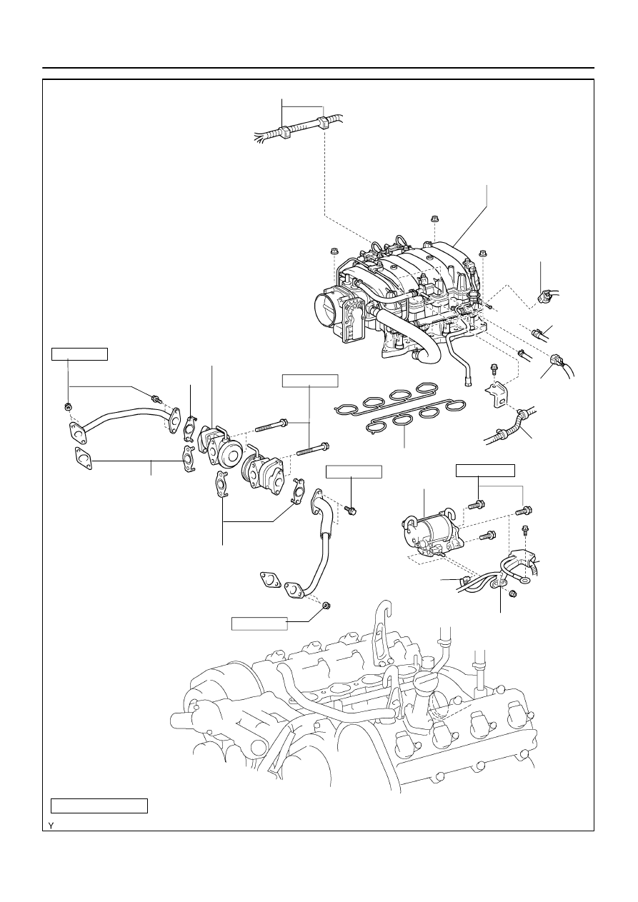
Injector Connector
VSV Connector
for EVAP
Starter Connector
Starter
Intake Manifold Assembly
Engine Wire and Clamp
Gasket
Non–reusable part
39 (400, 29)
Engine Wire
Protector
Fuel Return Hose
Engine Wire
N·m (kgf·cm, ft·lbf) : Specified torque
Gasket
Fuel Inlet Hose
Air Switching Valve No.2
Gasket
Gasket
10 (102, 7 )
10 (102, 7 )
10 (102, 7 )
10 (102, 7 )
–
STARTING
STARTER
ST–3
2877
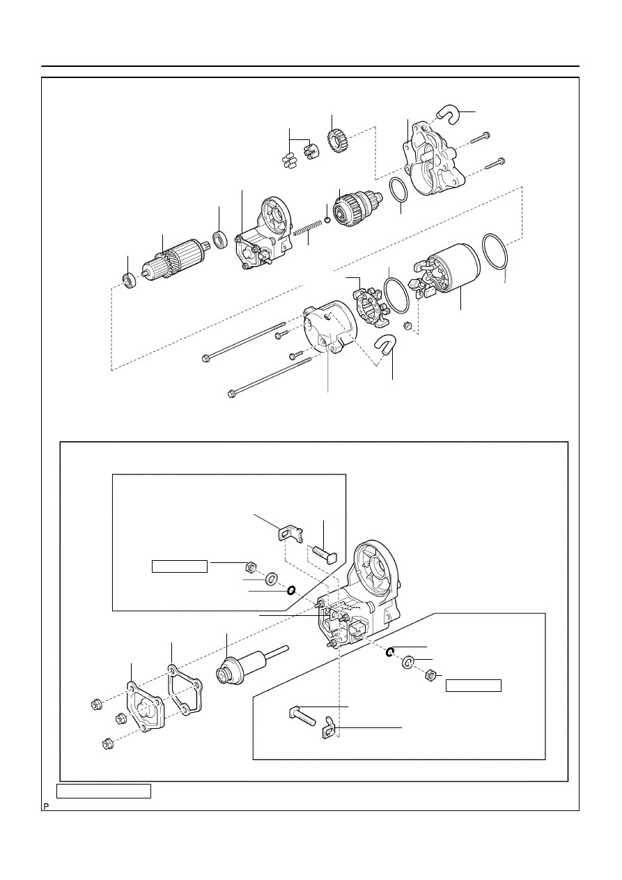
B13802
O–Ring
Idler Gear
Starter Housing
Assembly
Return Spring
Starter Clutch
Assembly
Steel Ball
Contact Plate
Rear Bearing
Armature
Magnetic Switch
Assembly
Bearing
Front Bearing
O–Ring
End Cover
Brush Holder
Magnetic Switch Assembly
Terminal Nut
O–Ring
Wave Washer
Terminal Bolt
Terminal C Kit Part
Lead Terminal
Plunger
Gasket
End Cover
Terminal Bolt
Wave Washer
O–Ring
Terminal Nut
Terminal 30 Kit Part
Non–reusable part
Dust Protector
Dust Protector
Field Frame (Field Coil)
17 (170, 13)
17 (170, 13)
N·m (kgf·cm, ft·lbf) : Specified torque
O–Ring
Contact Plate
ST–4
–
STARTING
STARTER
2878
ST08Z–07
B04548
B04549
Starter
Connector
Engine Wire Protector
–
STARTING
STARTER
ST–5
2879
REMOVAL
1.
REMOVE THROTTLE BODY COVER
2.
REMOVE INTAKE AIR CONNECTOR
3.
DISCONNECT CABLE FROM NEGATIVE (–) BATTERY
TERMINAL
4.
DISCONNECT THROTTLE BODY ASSEMBLY FROM
INTAKE MANIFOLD (See page
)
5.
REMOVE INTAKE MANIFOLD ASSEMBLY
(See page
6.
REMOVE AIR PUMP ASSEMBLY (See page
7.
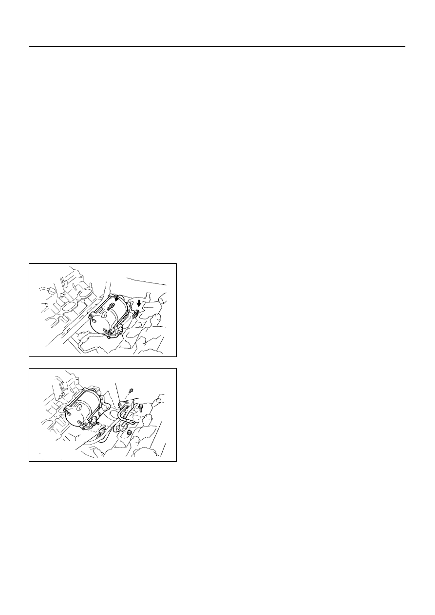
REMOVE STARTER
(a)
Remove the 2 bolts holding the starter from the cylinder
block.
(b)
Disconnect the starter from the cylinder block.
(c)
Disconnect the starter connector.
(d)
Remove the nut, bolt and disconnect the starter wire.
(e)
Remove the bolt, and disconnect the engine wire protec-
tor from the starter.
(f)
Remove the starter.
ST090–06
B12318
B12328
B13804
B13805
(2)
(3)
(1)
(4)
(5)
ST0948
Magnetic Finger
ST–6
–
STARTING
STARTER
2880
DISASSEMBLY
1.
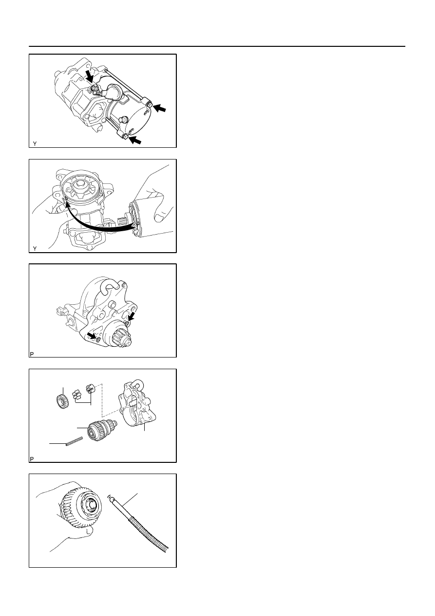
REMOVE FIELD FRAME AND ARMATURE
(a)
Remove the nut, and disconnect the lead wire from the
magnetic switch terminal.
Torque: 5.9 N·m (60 kgf·cm, 52 in.·lbf)
(b)
Remove the 2 through bolts.
Torque: 9.3 N·m (95 kgf·cm, 82 in.·lbf)
(c)
Pull out the field frame together with the armature from the
magnetic switch assembly.
NOTICE:
At the time of assembly, align the protrusion of the field
frame with the groove of the magnetic switch.
(d)
Remove the O–ring from the field frame.
HINT:
At the time of assembly, use a new O–ring.
2.
REMOVE STARTER HOUSING, CLUTCH ASSEMBLY
AND GEAR
(a)
Remove the 2 screws.
Torque: 9.3 N·m (95 kgf·cm, 82 in.·lbf)
(b)
Remove these parts from the magnetic switch assembly:
(1)
Starter housing
(2)
Return spring
(3)
Idler gear
(4)
Bearing
(5)
Starter clutch assembly
HINT:
At the time of assembly, please refer to the following items.
Apply grease to the return spring and insert the return spring
into the clutch shaft hole.
3.
REMOVE STEEL BALL
Using a magnetic finger, remove the steel ball from the clutch
shaft hole.
HINT:
At the time of assembly, apply grease to the steel ball and insert
the steel ball into the clutch shaft hole.
Нет комментариевНе стесняйтесь поделиться с нами вашим ценным мнением.
Текст