Toyota Sequoia (2005). Manual — part 955
AC3HO–02
I21378
I22633
2
1
AC–82
–
AIR CONDITIONING
REAR BLOWER MOTOR
3809
REAR BLOWER MOTOR
INSPECTION
1.
REMOVE REAR SEAT OUTER BELT FLOOR AN-
CHORS
2.
REMOVE BACK DOOR SCUFF PLATE
3.
REMOVE REAR DOOR SCUFF PLATE RH
4.
REMOVE REAR WINDOW SIDE GARNISH
5.
REMOVE REAR QUARTER TRIM PANEL RH
6.
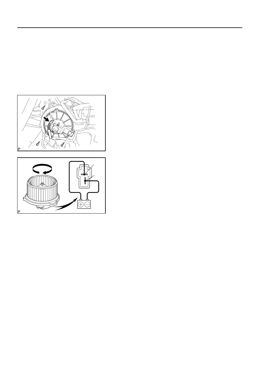
REMOVE BLOWER MOTOR
(a)
Disconnect the blower motor connector.
(b)
Remove the 3 screws and blower motor.
7.
INSPECT BLOWER MOTOR OPERATION
Connect the positive (+) lead from the battery to terminal 2 and
the negative (–) lead to terminal 1, then check that the motor op-
erates smoothly.
If operation is not as specified, replace the blower motor.
8.
INSTALL BLOWER MOTOR
9.
INSTALL REAR QUARTER TRIM PANEL RH
10.
INSTALL REAR WINDOW SIDE GARNISH
11.
INSTALL REAR DOOR SCUFF PLATE RH
12.
INSTALL BACK DOOR SCUFF PLATE
13.
INSTALL REAR SEAT OUTER BELT FLOOR AN-
CHORS
AC3HP–02
I21372
–
AIR CONDITIONING
BLOWER MOTOR LINEAR CONTROLLER
AC–83
3810
BLOWER MOTOR LINEAR
CONTROLLER
INSPECTION
1.
REMOVE GLOVE COMPARTMENT PARTS
2.
REMOVE LOWER NO. 2 FINISH PANEL
3.
REMOVE LOWER CENTER COVER
4.
REMOVE LOWER LH FINISH PANEL
5.
REMOVE NO. 4 HEATER TO REGISTER DUCT
6.
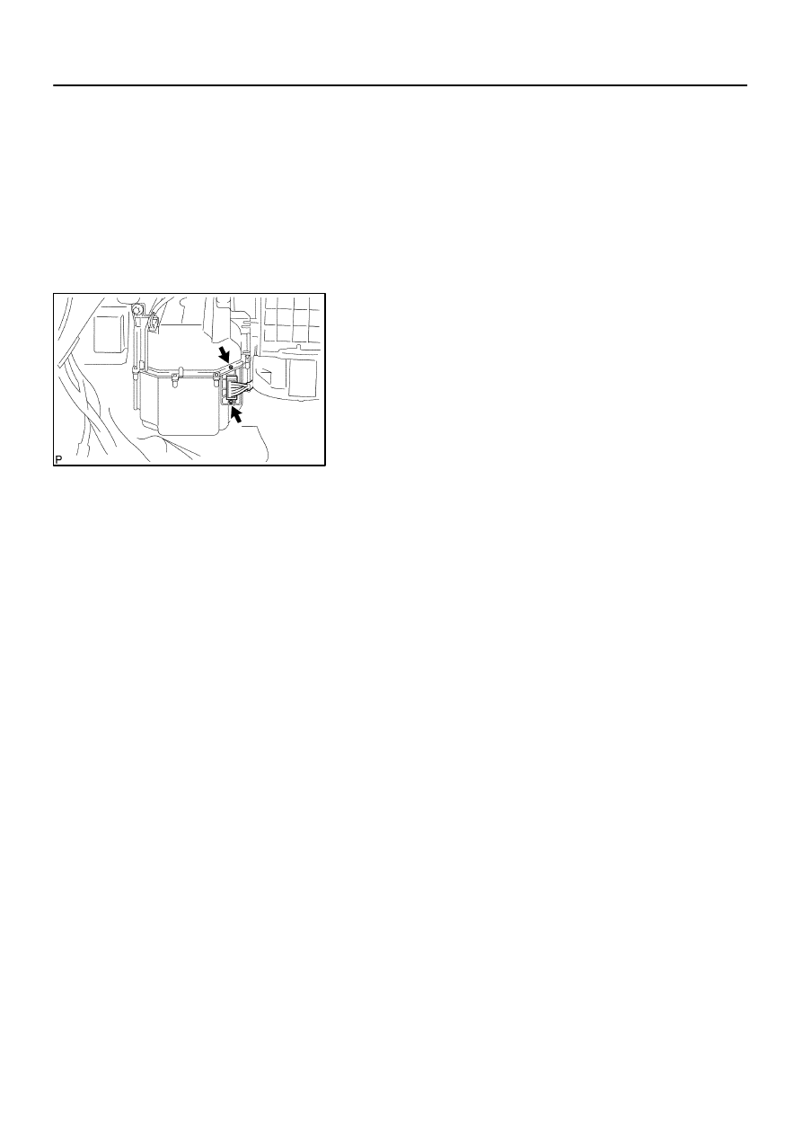
REMOVE BLOWER MOTOR LINEAR CONTROLLER
(a)
Disconnect the connector.
(b)
Remove the 2 screws and blower motor linear controller.
7.
INSPECT BLOWER MOTOR LINEAR CONTROLLER
(See page
8.
INSTALL BLOWER MOTOR LINEAR CONTROLLER
(a)
Install the blower motor linear controller with the 2 screws.
(b)
Connect the connector.
9.
INSTALL NO. 4 HEATER TO REGISTER DUCT
10.
INSTALL LOWER LH FINISH PANEL
11.
INSTALL LOWER CENTER COVER
12.
INSTALL LOWER NO. 2 FINISH PANEL
13.
INSTALL GLOVE COMPARTMENT PARTS
AC3HQ–02
I21379
I22616
1
2
4
I17711
3
4
AC–84
–
AIR CONDITIONING
POWER TRANSISTOR (for Rear A/C)
3811
POWER TRANSISTOR (for Rear
A/C)
INSPECTION
1.
REMOVE REAR SEAT OUTER BELT FLOOR AN-
CHORS
2.
REMOVE BACK DOOR SCUFF PLATE
3.
REMOVE REAR DOOR SCUFF PLATE RH
4.
REMOVE REAR WINDOW SIDE GARNISH
5.
REMOVE REAR QUARTER TRIM PANEL RH
6.
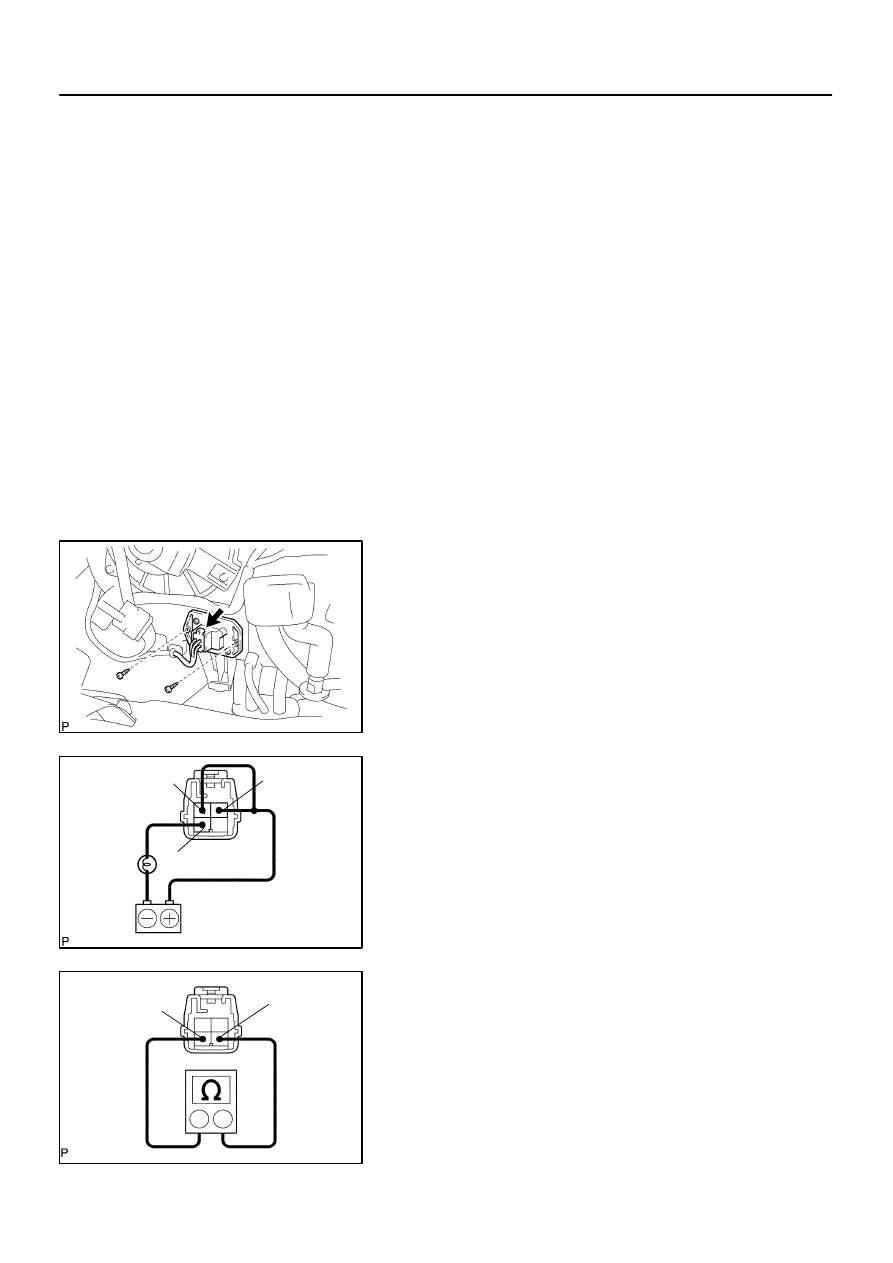
REMOVE REAR POWER TRANSISTOR
(a)
Disconnect the connector.
(b)
Remove the 2 screws and the rear power transistor.
7.
INSPECT POWER TRANSISTOR OPERATION
(a)
Connect the positive (+) lead to terminal 1 through a
12 V – 3.4 W test bulb and the negative (–) lead to
terminal 4.
(b)
Check the test bulb lights up when another positive (+)
lead is connected to terminal 2 through a 12 V – 3.4 W test
bulb.
If operation is not as specified, replace the power transistor.
8.
INSPECT POWER TRANSISTOR RESISTANCE
Measure the resistance between terminals 3 and 4.
Standard resistance: 2.0 to 2.4 k
Ω
If resistance is not as specified, replace the power transistor.
9.
INSTALL REAR POWER TRANSISTOR
10.
INSTALL REAR QUARTER TRIM PANEL RH
11.
INSTALL REAR WINDOW SIDE GARNISH
12.
INSTALL REAR DOOR SCUFF PLATE RH
13.
INSTALL BACK DOOR SCUFF PLATE
–
AIR CONDITIONING
POWER TRANSISTOR (for Rear A/C)
AC–85
3812
14.
INSTALL REAR SEAT OUTER BELT FLOOR AN-
CHORS
Нет комментариевНе стесняйтесь поделиться с нами вашим ценным мнением.
Текст