Toyota Sequoia (2005). Manual — part 177

A19655
A20059
STSW
ACCR
STAR
(NE)
Engine Speed
Starter
Park/Neutral
Position SW
N
P
ST Relay
ACC Cut
Relay
Ignition
SW
ACC
ST2
ACCR
STSW
STAR
Battery
ECM
–
DIAGNOSTICS
ENGINE
DI–503
697
Cranking Hold Function Circuit
CIRCUIT DESCRIPTION
The starter is controlled by the ECM, when the ECM detects a start signal (STSW) from the ignition switch,
this system monitors the engine speed (NE) and continues to operate the starter until it has determined that
the engine has started (engine speed reaches approximately 500 rpm). If the engine is already running and
the ignition switch is turned to START, the ECM will not operate the starter.
WIRING DIAGRAM
Refer to DTC P0617 on page
.
INSPECTION PROCEDURE
Hand–held tester:
1
Check operation of engine cranking.
CHECK:
When turning the ignition switch to the START position, check whether the starter motor starts.
OK:
Starter motor starts.
OK
Check for intermittent problems (See page
NG
DID8M–01
B17411
STA (+)
E1 (–)
STSW(+)
E6
DI–504
–
DIAGNOSTICS
ENGINE
698
2
Connect hand–held tester, and check STA signal.
PREPARATION:
(a)
Connect the hand–held tester to the DLC3.
(b)
Turn the ignition switch ON, and push the hand–held tester main switch ON.
(c)
Enter the following menu: DIAGNOSIS / ENHANCED OBD II / DATA LIST / ALL / STARTER SIG.
CHECK:
Read the STA signal on the hand–held tester while the starter operates.
OK:
Ignition Switch Position
ON
START
STARTER SIG
OFF
ON
NG
Go to step 5.
OK
3
Check voltage between terminal STAR, STSW and E1 of ECM connector.
CHECK:
Measure the voltage between the terminals of the E6 ECM con-
nectors, while cranking the engine (ignition switch START posi-
tion).
OK:
Standard:
Tester Connection
Specified Condition
STA (E6–11) – E1 (E6–1)
9 to 14 V
STSW (E6–12) – E1 (E6–1)
9 to 14 V
RESULT:
Terminal STAR
Terminal STSW
Proceed to
9 to 14 V
9 to 14 V
A
0 V
9 to 14 V
B
0 V
0 V
C
B
Replace ECM (See page
C
Go to step 9.
A
D14154
Component Side:
A19288
–
DIAGNOSTICS
ENGINE
DI–505
699
4
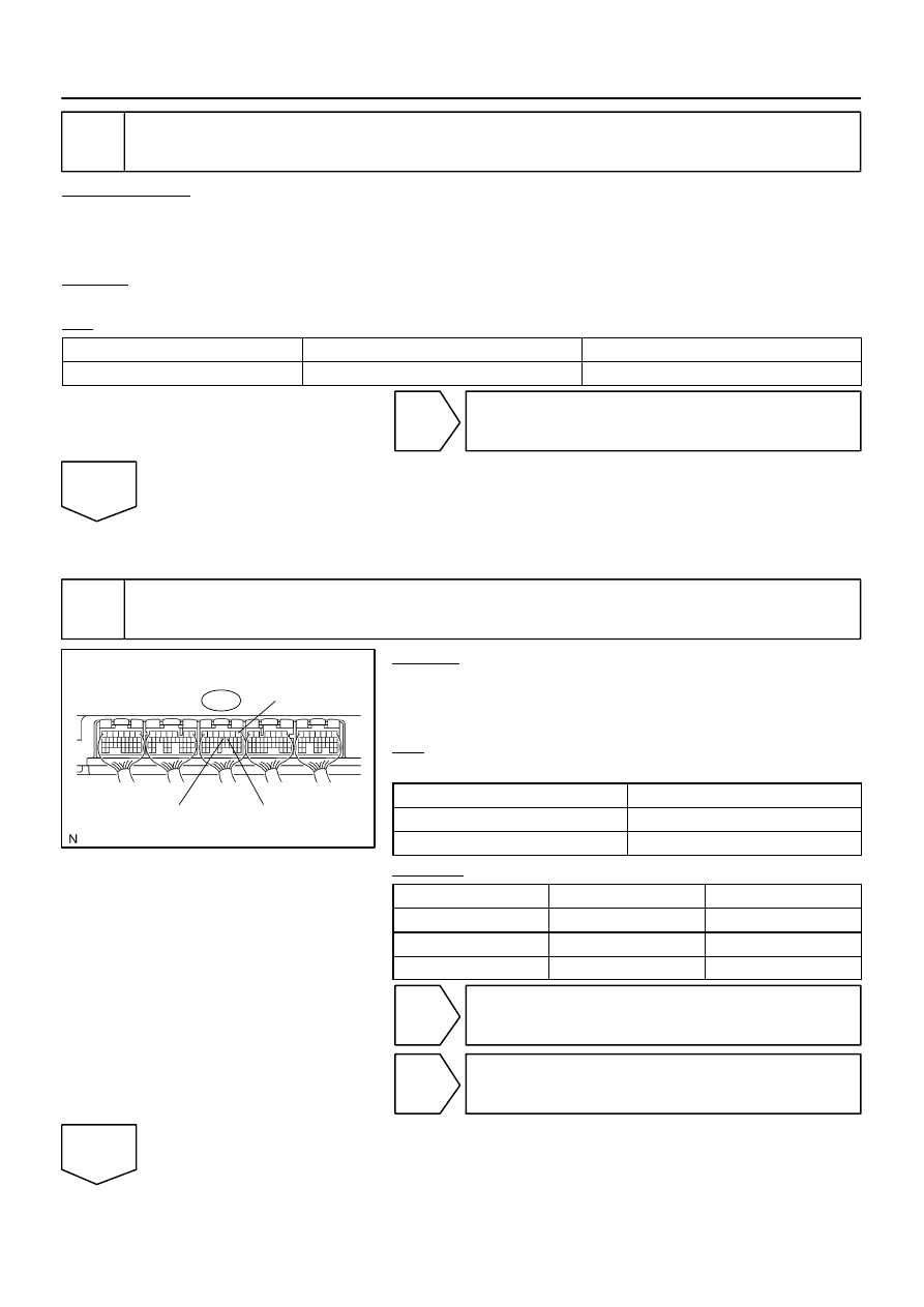
Check park/neutral position switch.
PREPARATION:
Remove the P1 park/neutral position switch connector.
CHECK:
Check resistance between each terminal shown below when
the shift lever is moved to each range.
Shift range
Terminal No. to continuity
P
1 – 3
6 – 9
R
2 – 3
–
N
3 – 5
6 – 9
D
3 – 7
–
2
3 – 4
–
L
3 – 8
–
OK:
Below 1
Ω
NG
Replace the park/neutral position switch.
OK
Check and repair harness and connector be-
tween park/neutral position switch and ECM.
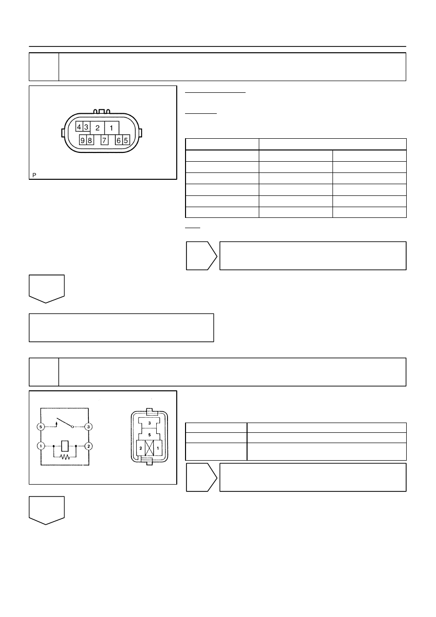
5
Check starter relay.
(a)
Remove the starter relay from the engine room R/B.
(b)
Inspect the starter relay.
Standard:
Tester Connection
Specified Condition
3 – 5
10 k
Ω
or higher
3 – 5
Below 1
Ω
(Apply battery voltage to terminals 1 and 2)
NG
Replace starter relay.
OK
A23563
Wire Harness Side
Park/Neutral position switch Connector
N1
A21559
Engine Room R/B No.2
Starter Relay
DI–506
–
DIAGNOSTICS
ENGINE
700
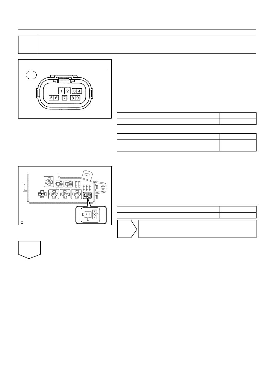
6
Check for open and short in harness and connector between park/neutral posi-
tion switch and starter relay.
(a)
Check the harness and the connector between the park/
neutral position switch connector and the starter relay.
(1)
Disconnect the park/neutral position switch con-
nector.
(2)
Remove the starter relay from the engine room R/B.
(3)
Check for resistance between the wire harness side
connectors.
Standard (Check for open):
Symbols (Terminal No.)
Specified condition
Park/Neutral position switch (N1–6) – Starter relay (1)
Below 1
Ω
Standard (Check for short):
Symbols (Terminal No.)
Specified condition
Park/Neutral position switch (N1–6) or Starter relay (1)
– Body ground
10 k
Ω
or higher
(b)
Check the harness and the connector between the starter
relay and the body ground.
(1)
Remove the starter relay from the engine room R/B.
(2)
Check for resistance between the starter relay and
the body ground.
Standard (Check for open):
Symbols (Terminal No.)
Specified condition
Starter relay (2) – Body ground
Below 1
Ω
NG
Repair or replace harness or connector.
OK
Нет комментариевНе стесняйтесь поделиться с нами вашим ценным мнением.
Текст