Toyota Sequoia (2005). Manual — part 632

I28847
SG–TAM
TAM
I19
Integration Control and Panel:
–
DIAGNOSTICS
AIR CONDITIONING SYSTEM
DI–2323
2517
INSPECTION PROCEDURE
1
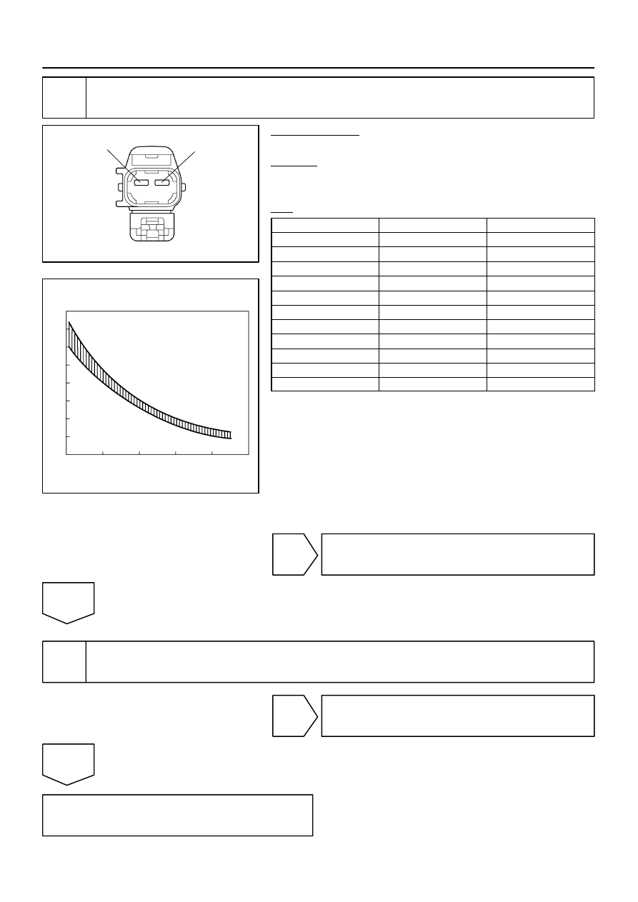
Check voltage between terminals TAM and SG–TAM of integration control and
panel.
PREPARATION:
Remove the integration control and panel with connectors still
connected.
CHECK:
(a)
Turn the ignition switch to ON.
(b)
Measure the voltage between terminals TAM and SG–
TAM of the integration control and panel connector at
each temperature.
OK:
Voltage :
at 25
°
C (77
°
F) : 1.35 to 1.75 V
at 40
°
C (104
°
F) : 0.85 to 1.25 V
HINT:
As the temperature increases, the voltage decreases.
NG
OK
Proceed to next circuit inspection shown in problem symptoms table (See page
ever, if DTC 12 is displayed, replace integration control and panel.
I08311
2
1
I28970
Resistance (k
Ω
)
Temperature
4.0
2.0
3.5
1.5
0.0
10
3.0
1.0
2.5
0.5
20
30
40
50
60
68
86
104
122
140
(
C)
(
F)
50
DI–2324
–
DIAGNOSTICS
AIR CONDITIONING SYSTEM
2518
2
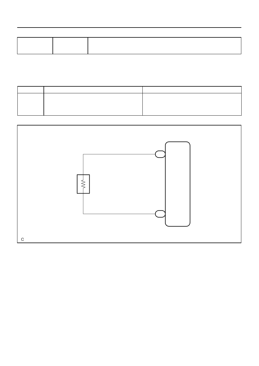
Check ambient temperature sensor.
PREPARATION:
Disconnect the ambient temperature sensor connector.
CHECK:
Measure the resistance between terminals 1 and 2 of the ambi-
ent temperature sensor connector at each temperature.
OK:
Tester connection
Condition
Specified condition
1–2
10
C (50
F)
3.00 to 3.73 k
Ω
1–2
15
C (59
F)
2.45 to 2.88 k
Ω
1–2
20
C (68
F)
1.95 to 2.30 k
Ω
1–2
25
C (77
F)
1.60 to 1.80 k
Ω
1–2
30
C (86
F)
1.28 to 1.47 k
Ω
1–2
35
C (95
F)
1.00 to 1.22 k
Ω
1–2
40
C (104
F)
0.80 to 1.00 k
Ω
1–2
45
C (113
F)
0.65 to 0.85 k
Ω
1–2
50
C (122
F)
0.50 to 0.70 k
Ω
1–2
55
C (131
F)
0.44 to 0.60 k
Ω
1–2
60
C (140
F)
0.36 to 0.50 k
Ω
NOTICE:
Even slightly touching the sensor may change the re-
sistance value. Be sure to hold the connector of the
sensor.
When measuring, the sensor temperature must be
the same as the ambient temperature.
HINT:
As the temperature increases, the resistance decreases (see
the graph on the left).
NG
Replace ambient temperature sensor.
OK
3
Check harness and connector between ambient temperature sensor and integra-
tion control and panel (See page
).
NG
Repair or replace harness or connector.
OK
Replace integration control and panel.
I28833
A13
A/C Evaporator
Temp. Sensor
(Front)
1
2
2
Integration Control and Panel
TE
SG–TE
W–G
G–B
4
I20
I20
–
DIAGNOSTICS
AIR CONDITIONING SYSTEM
DI–2325
2519
DTC
13
Front Evaporator Temperature Sensor Cir-
cuit
CIRCUIT DESCRIPTION
This sensor detects the temperature inside the cooling unit and sends the appropriate signals to the integra-
tion control and panel.
DTC No.
Detection Item
Trouble Area
13
Open or short in front evaporator temperature sensor circuit.
Front evaporator temp. sensor
Harness or connector between front evaporator temp. sensor
and integration control and panel
Integration control and panel
WIRING DIAGRAM
DIDKV–01
I28847
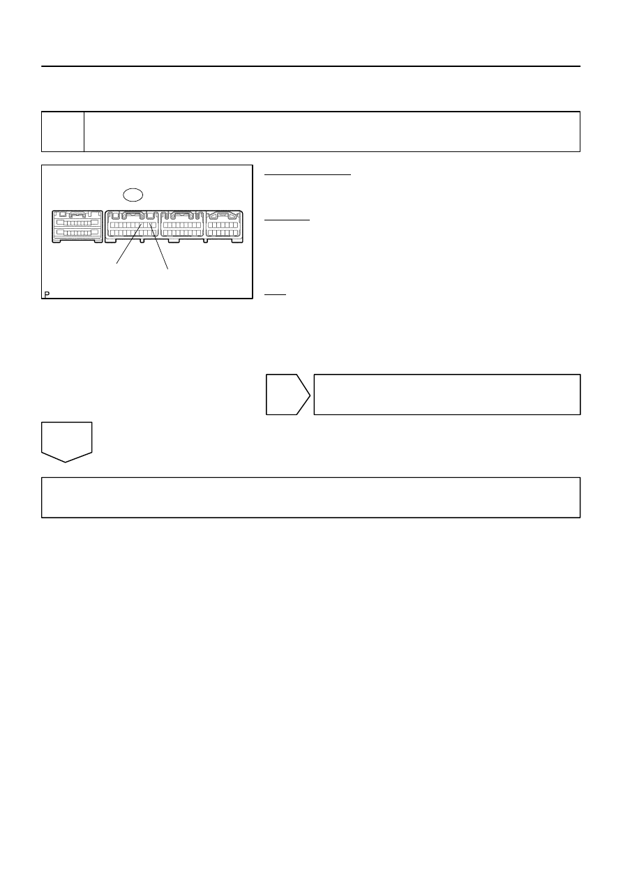
SG–TE
TE
I20
Integration Control and Panel:
DI–2326
–
DIAGNOSTICS
AIR CONDITIONING SYSTEM
2520
INSPECTION PROCEDURE
1
Check voltage between terminals TE and SG–TE of integration control and pan-
el.
PREPARATION:
Remove the integration control and panel with connectors still
connected.
CHECK:
(a)
Turn the ignition switch to ON.
(b)
Measure the voltage between terminals TE and SG–TE
of the integration control and panel connector at each
temperature.
OK:
Voltage :
at 0
°
C (32
°
F) : 2.0 to 2.4 V
at 15
°
C (59
°
F) : 1.4 to 1.8 V
HINT:
As the temperature increases, the voltage decreases.
NG
OK
Proceed to next circuit inspection shown in problem symptoms table (See page
ever, if DTC 13 is displayed, replace integration control and panel.
Нет комментариевНе стесняйтесь поделиться с нами вашим ценным мнением.
Текст