Toyota Sequoia (2005). Manual — part 758
R13276
SST
–
SUSPENSION AND AXLE
FRONT AXLE HUB
SA–25
3021
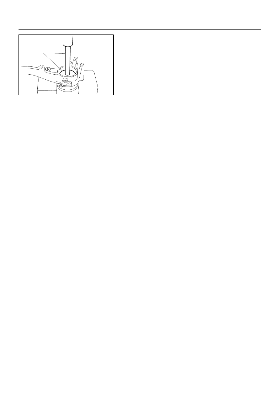
(b)
Using SST and a press, remove the bearing from the
steering knuckle.
SST
09950–60020 (09951–00810),
09950–70010 (09951–07150)
SA146–08
R13277
SST
SST
R13278
SST
SST
R13279
SST
R13215
SST
R13418
SST
SA–26
–
SUSPENSION AND AXLE
FRONT AXLE HUB
3022
REASSEMBLY
1.
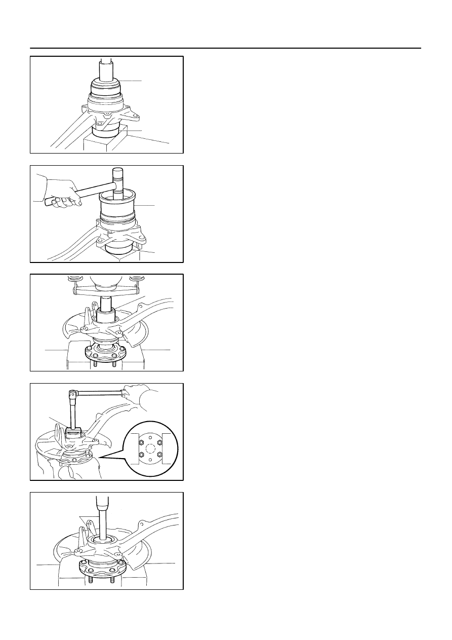
INSTALL NEW BEARING
(a)
Using SST and a press, install a new bearing to the steer-
ing knuckle.
SST
09527–17011, 09950–60020 (09951–00910)
(b)
Using snap ring pliers, install a new snap ring.
2.
INSTALL NEW OIL SEAL (OUTSIDE)
(a)
Using SST and a plastic hammer, install a new oil seal
(outside).
SST
09223–15030, 09527–17011
(b)
Coat MP grease to the oil seal lip.
3.
INSTALL AXLE HUB TO STEERING KNUCKLE
(a)
Install the dust cover to the steering knuckle with the 4
bolts.
Torque: 18 N·m (185 kgf·cm, 13 ft·lbf)
(b)
Using SST and a press, install the axle hub to the steering
knuckle.
SST
09649–17010
4.
INSTALL SPEED SENSOR ROTOR
NOTICE:
Do not scratch the serration of the speed sensor rotor.
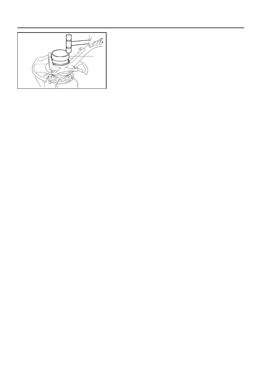
5.
2WD:
INSTALL NEW LOCK NUT
(a)
Using SST, install and torque a new lock nut to the axle
hub.
SST
09318–12010
Torque: 274 N·m (2,800 kgf·cm, 203 ft·lbf)
(b)
Using a chisel and hammer, stake the lock nut.
6.
4WD:
INSTALL BEARING SPACER
Using SST and a press, install the bearing spacer.
SST
09950–60010 (09951–00650),
09950–70010 (09951–07150)
7.
2WD:
INSTALL GREASE CAP
R13280
SST
–
SUSPENSION AND AXLE
FRONT AXLE HUB
SA–27
3023
8.
4WD:
INSTALL NEW OIL SEAL (INSIDE)
(a)
Using SST and a plastic hammer, install a new oil seal (in-
side).
SST
09527–17011
HINT:
Lightly strike the SST on its circumference evenly.
(b)
Coat MP grease to the oil seal lip.
SA23J–05
SA–28
–
SUSPENSION AND AXLE
FRONT AXLE HUB
3024
INSTALLATION
1.
INSTALL STEERING KNUCKLE
(a)
4WD:
Insert the drive shaft into the axle hub and temporarily tighten the nut.
NOTICE:
Be careful not to damage the oil seal and drive shaft boot.
(b)
Connect the steering knuckle to the upper suspension arm.
(c)
Install the nut and a new cotter pin.
If the holes for the cotter pin are not aligned, tighten the nut further up to 60
°
.
Torque: 105 N·m (1,100 kgf·cm, 77 ft·lbf)
2.
CONNECT LOWER BALL JOINT
Connect the lower ball joint to the steering knuckle with the 4 bolts.
Torque: 65 N·m (663 kgf·cm, 48 ft·lbf)
3.
INSTALL SHOCK ABSORBER (See page
4.
INSTALL BRAKE CALIPER
(a)
Install the disc, brake caliper and 2 bolts.
Torque: 123 N·m (1,250 kgf·cm, 90 ft·lbf)
(b)
Install the brake line clamp to the steering knuckle with the bolt.
Torque: 28 N·m (285 kgf·cm, 21 ft·lbf)
5.
CONNECT SPEED SENSOR AND WIRE HARNESS CLAMP
Connect the speed sensor and wire harness clamp to the steering knuckle with the 2 bolts.
Torque: 8.0 N·m (82 kgf·cm, 71 ft·lbf)
6.
4WD:
INSTALL DRIVE SHAFT LOCK NUT
(a)
While applying the brakes, tighten the nut.
Torque: 235 N·m (2,400 kgf·cm, 173 ft·lbf)
(b)
Install the lock cap and a new cotter pin.
If the holes for the cotter pin are not aligned, tighten the nut further up to 60
°
.
7.
INSTALL GREASE CAP
8.
INSTALL FRONT WHEEL
Torque: 110 N·m (1,150 kgf·cm, 83 ft·lbf)
9.
DEPRESS BRAKE PEDAL SEVERAL TIMES
10.
CHECK FRONT WHEEL ALIGNMENT (See page
)
11.
CHECK SPEED SENSOR SIGNAL (See page
12.
PERFORM ZERO POINT CALIBRATION OF STEERING ANGLE, MASTER CYLINDER PRES-
SURE, YAW RATE AND DECELERATION SENSORS (See page
Нет комментариевНе стесняйтесь поделиться с нами вашим ценным мнением.
Текст