Toyota Sequoia (2005). Manual — part 703
B17473
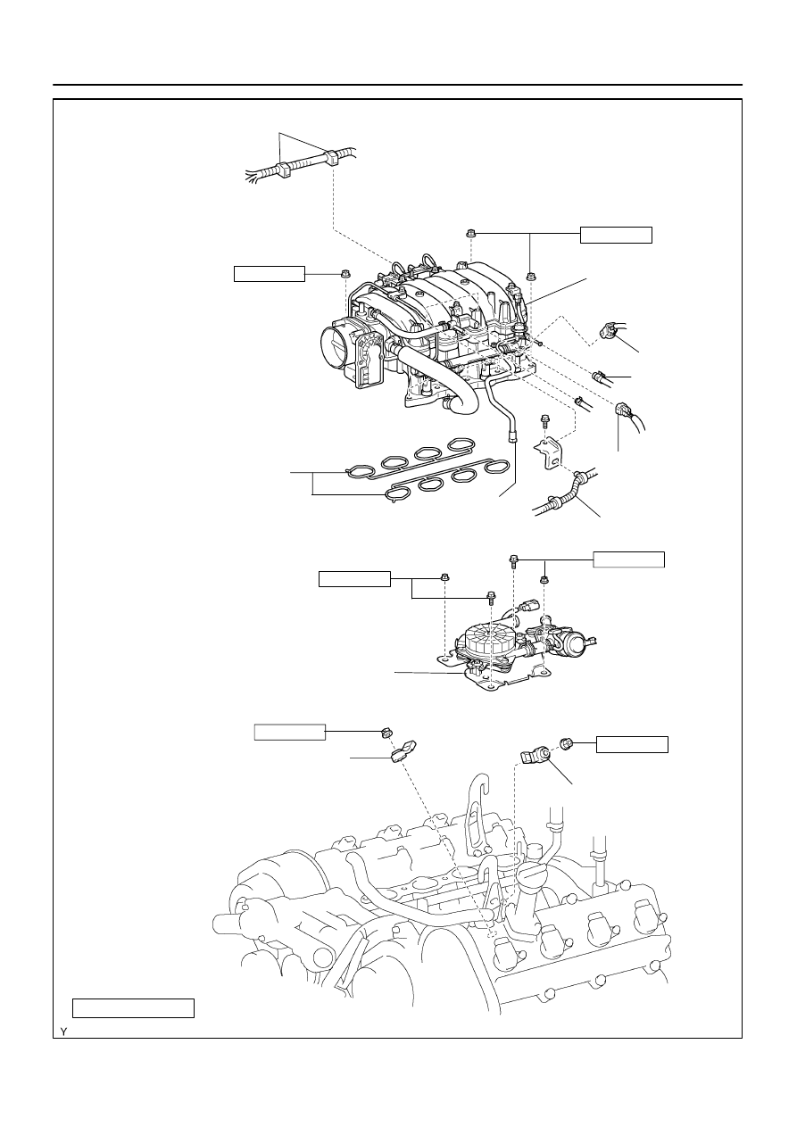
Engine Wire Clamp
Injector Connector
Gasket
18 (185, 13)
N·m (kgf·cm, ft·lbf)
: Specified torque
Non–reusable part
18 (185, 13)
Knock Sensor 2
VSV Connector
for EVAP
Fuel Inlet Hose
Knock Sensor 1
Fuel Return Hose
Intake Manifold
Assembly
Engine Wire
20 (204, 15)
20 (204, 15)
Air Pump Assembly
16 (163, 12)
16 (163, 12)
–
SFI
KNOCK SENSOR
SF–67
2801
SF1XU–01
B17474
B17475
B17503
Engine
Rear
Engine
Rear
Upper
Upper
0
°
– 10
°
0
°
– 10
°
SF–68
–
SFI
KNOCK SENSOR
2802
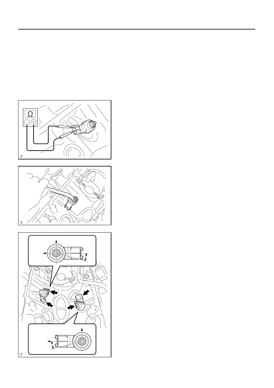
INSPECTION
1.
REMOVE THROTTLE BODY COVER
2.
REMOVE INTAKE AIR CONNECTOR
3.
REMOVE INTAKE MANIFOLDS ASSEMBLY
(See page
4.
INSPECT KNOCK SENSORS 1 AND 2
(a)
Disconnect the knock sensor connectors.
(b)
Using an ohmmeter, measure the resistance between ter-
minals.
Resistance: 120 to 280 k
Ω
at 20
°
C (68
°
F)
HINT:
If the resistance is not as specified, replace the sensor.
5.
REMOVE KNOCK SENSOR
(a)
Disconnect the 2 knock sensor connectors.
(b)
Remove the 2 nuts and 2 knock sensors.
6.
INSTALL KNOCK SENSOR
(a)
Install the 2 knock sensors with the 2 nuts as shown in the
illustration.
Torque: 20 N·m (204 kgf·cm, 15 ft·lbf)
(b)
Connect the 2 knock sensor connectors.
7.
INSTALL INTAKE MANIFOLD ASSEMBLY
(See page
)
8.
INSTALL INTAKE AIR CONNECTOR
9.
INSTALL THROTTLE BODY COVER
SF1XV–01
B17504
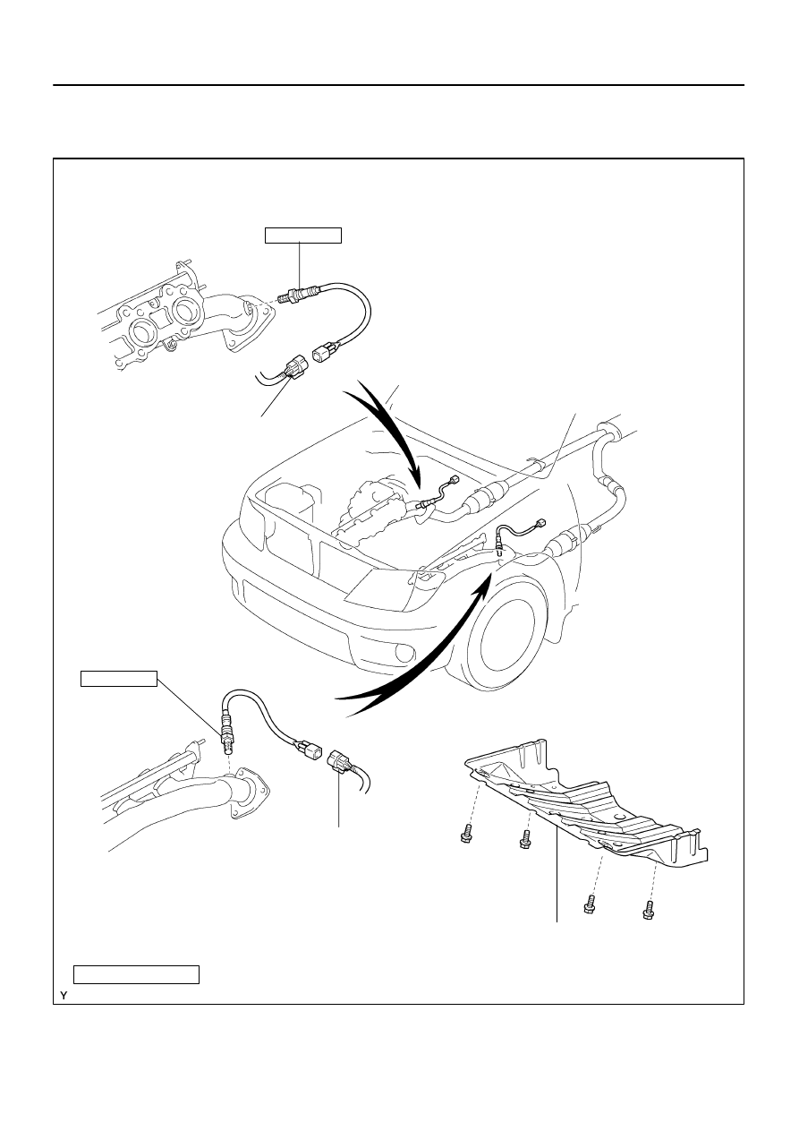
N·m (kgf·cm, ft·lbf)
Non–reusable part
: Specified torque
Air–fuel Ratio Sensor
Engine Under Cover
Bank 2 Sensor 1
Bank 1 Sensor 1
Air–fuel Ratio
Sensor Connector
Air–fuel Ratio Sensor
44 (450, 32)
Air–fuel Ratio Sen-
sor Connector
44 (450, 32)
–
SFI
AIR–FUEL RATIO (A/F) SENSOR
SF–69
2803
AIR–FUEL RATIO (A/F) SENSOR
COMPONENTS
SF1XW–01
B17505
+B
HT
B17512
C2
C1
A2A–
A2A+
E1
B2
B3
B1
A1A+
A1A–
SF–70
–
SFI
AIR–FUEL RATIO (A/F) SENSOR
2804
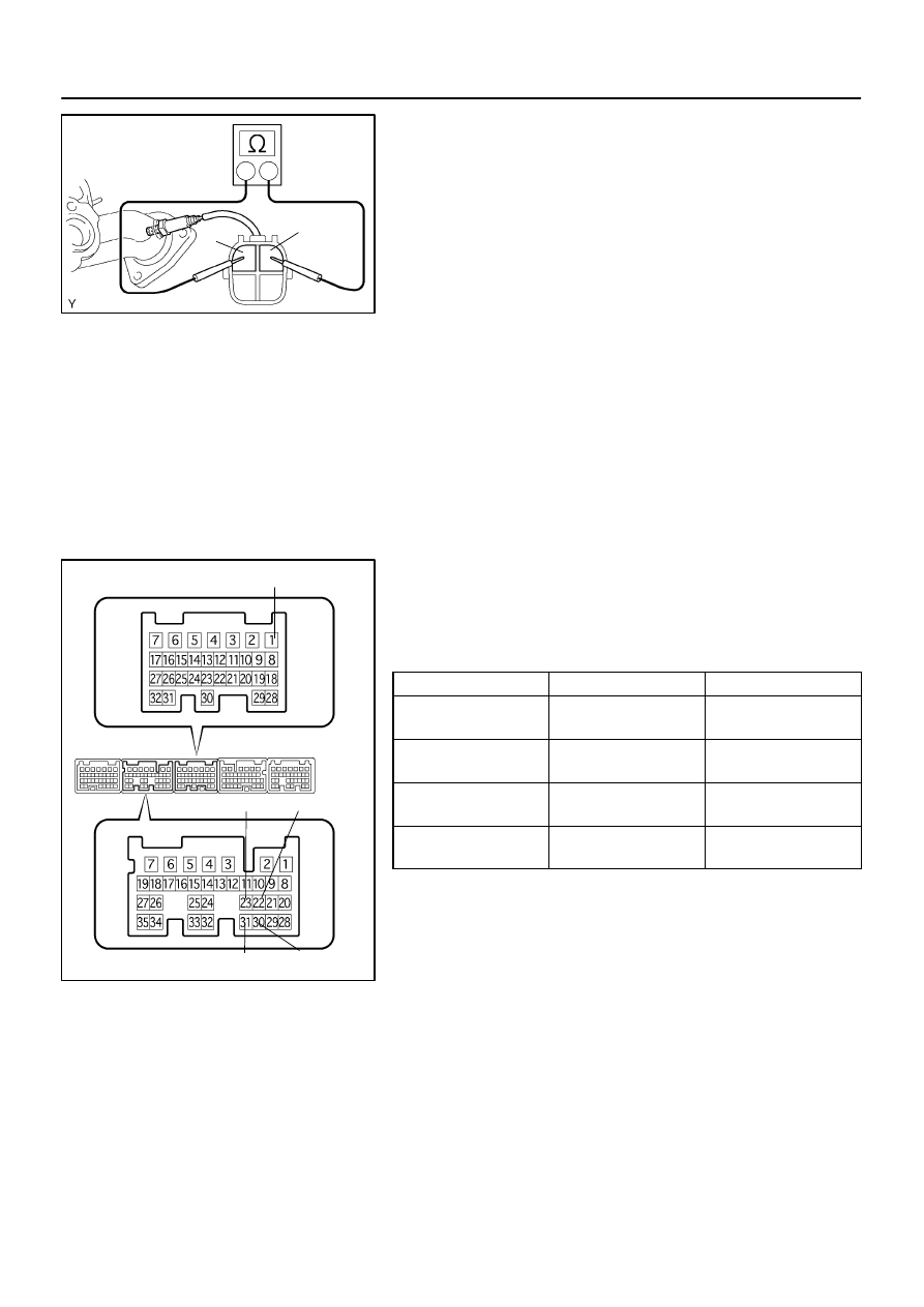
INSPECTION
1.
INSPECT HEATER RESISTANCE OF AIR FUEL RATIO
SENSOR
(a)
Disconnect the air fuel ratio sensor connector.
(b)
Using an ohmmeter, measure the resistance between ter-
minals +B and HT.
Resistance 11 to 16 k
Ω
at 20
°
C (68
°
F)
If the resistance is not as specified, replace the sensor.
Torque: 44 N·m (450 kgf·cm, 32 ft·lbf)
(c)
Reconnect the air fuel ratio sensor connector.
2.
INSPECT OPERATION OF AIR FUEL RATIO SENSOR
(See page
)
3.
INSPECT AIR–FUEL RATIO COMPENSATION SYS-
TEM
(a)
Measure the voltage between the terminals of the ECM
connectors.
Standard:
Tester Connection
Condition
Specified Condition
B2–22 (A1A+)
– B1–1 (E1)
Ignition switch ON
3.3 V
B2–30 (A1A–)
– B1–1 (E1)
Ignition switch ON
2.9 V
B2–23 (A2A+)
– B1–1 (E1)
Ignition switch ON
3.3 V
B2–31 (A2A–)
– B1–1 (E1)
Ignition switch ON
2.9 V
NOTICE:
Connect test leads from the back side of the connector. The
connectors should not be disconnected from the ECM.
HINT:
The voltage between the terminals of the ECM is kept constant
regardless of the voltage of the A/F sensor.
Нет комментариевНе стесняйтесь поделиться с нами вашим ценным мнением.
Текст