Toyota Sequoia (2005). Manual — part 881
BE268–04
I08215
Lifter
Up
Down
Reclining
Tilt
Up
Down
Front
Back
Forward
Rear
I18601
Forward
Front
Rear
Back
–
BODY ELECTRICAL
POWER SEAT CONTROL SYSTEM
BE–109
3513
INSPECTION
1.
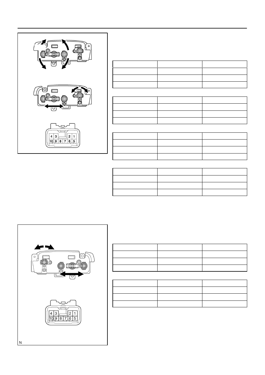
INSPECT DRIVER’S POWER SEAT SWITCH CONTI-
NUITY (w/o Driving Position Memory)
Slide Switch:
Switch position
Tester connection
Specified condition
FRONT
1 – 9, 4 – 6
Continuity
OFF
4 – 6 – 9
Continuity
BACK
1 – 6, 4 – 9
Continuity
Front Tilt Switch:
Switch position
Tester connection
Specified condition
UP
1 – 10, 4 – 5
Continuity
OFF
4 – 5 – 10
Continuity
DOWN
1 – 5, 4 – 10
Continuity
Rear Lifter Switch:
Switch position
Tester connection
Specified condition
UP
1 – 7, 4 – 8
Continuity
OFF
4 – 7 – 8
Continuity
DOWN
1 – 8, 4 – 7
Continuity
Reclining Switch:
Switch position
Tester connection
Specified condition
FORWARD
1 – 3, 2 – 4
Continuity
OFF
2 – 3 – 4
Continuity
REAR
1 – 2, 3 – 4
Continuity
If continuity is not as specified, replace the switch.
2.
INSPECT PASSENGER’S POWER SEAT SWITCH
CONTINUITY
Slide Switch:
Switch position
Tester connection
Specified condition
FRONT
1 – 9, 4 – 6
Continuity
OFF
4 – 6 – 9
Continuity
BACK
1 – 6, 4 – 9
Continuity
Reclining Switch:
Switch position
Tester connection
Specified condition
FORWARD
1 – 3, 2 – 4
Continuity
OFF
2 – 3 – 4
Continuity
REAR
1 – 2, 3 – 4
Continuity
If continuity is not as specified, replace the switch.
I27710
Forward
Release
I07253
(a)
(b)
2
1
1
2
I11936
2
1
I11937
2
1
I07254
(a)
(b)
2
1
1
2
BE–110
–
BODY ELECTRICAL
POWER SEAT CONTROL SYSTEM
3514
3.
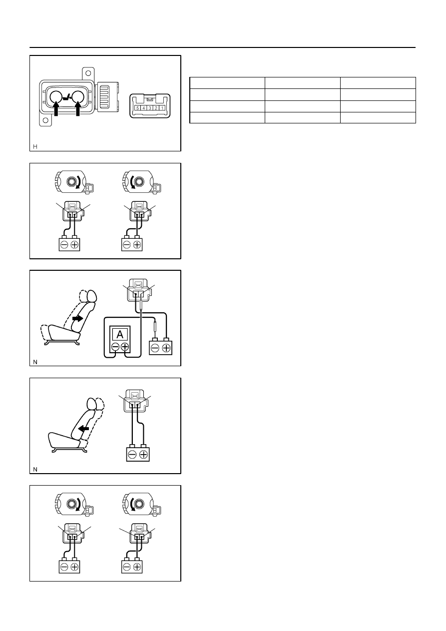
INSPECT DRIVER’S LUMBAR SUPPORT CONTROL
SWITCH CONTINUITY
Switch position
Tester connection
Specified condition
Forward
1 – 2, 3 – 4
Continuity
OFF
1 – 2, 4 – 5
Continuity
Release
1 – 3, 4 – 5
Continuity
If continuity is not as specified, replace the switch.
4.
INSPECT SLIDE MOTOR OPERATION
(a)
Connect the positive (+) lead from the battery to terminal
1 and the negative (–) lead to terminal 2, check that the
motor turns clockwise.
(b)
Reverse the polarity, check that the motor turns counter-
clockwise.
If operation is not as specified, replace the seat adjuster.
5.
INSPECT SLIDE MOTOR PTC THERMISTOR OPERA-
TION
( ): Passenger Side
(a)
Connect the positive (+) lead from the battery to terminal
2 (1), the positive (+) lead from the ammeter to terminal
1 (2) and the negative (–) lead to the battery negative (–)
terminal, then move the seat cushion to the rear position.
(b)
Continue to apply voltage, check that current changes to
less than 1 ampere within 4 to 90 seconds.
(c)
Disconnect the leads from terminals.
(d)
Approximately 60 seconds later, connect the positive (+)
lead from the battery to terminal 1 (2) and the negative (–)
lead to terminal 2 (1), check that the seat cushion begins
to move forwards.
If operation is not as specified, replace the seat adjuster.
6.
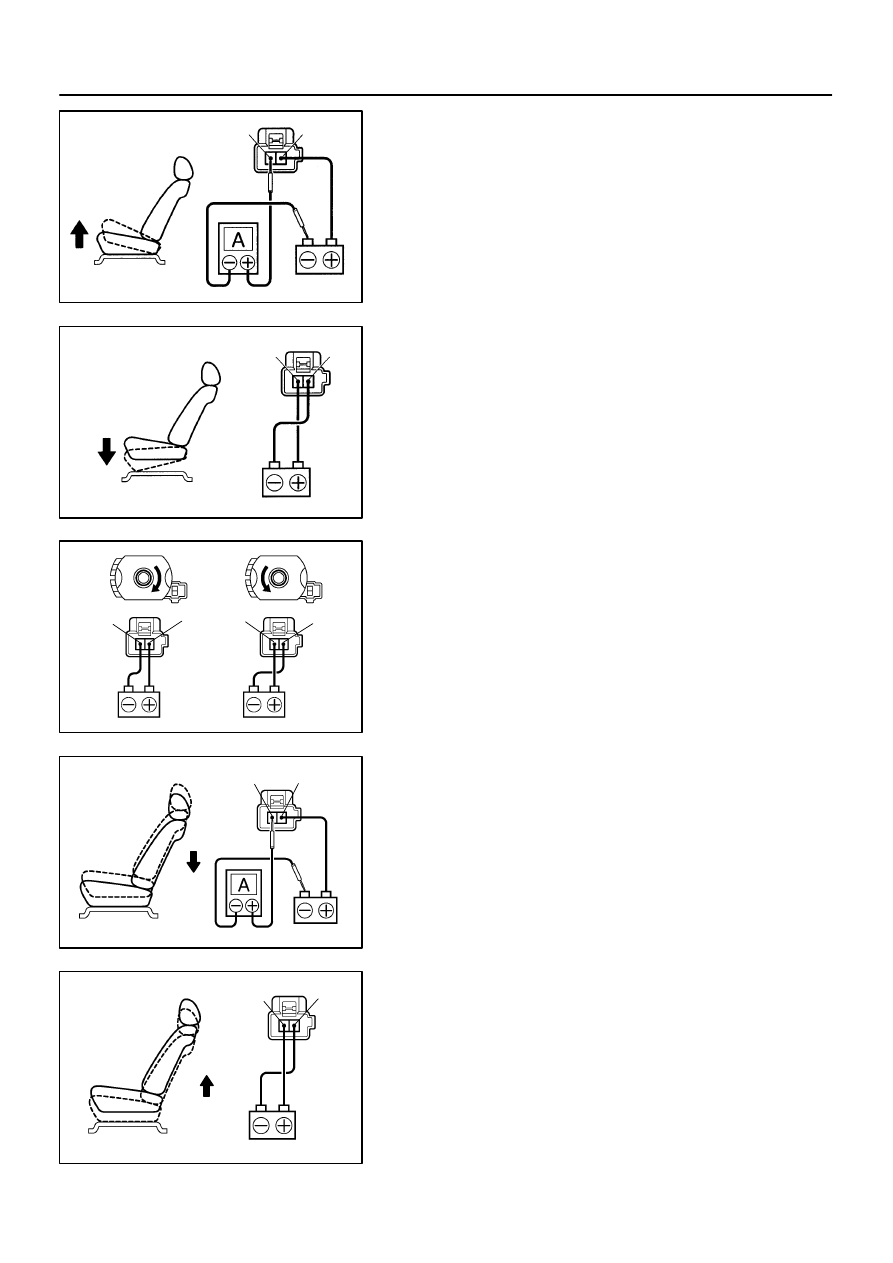
INSPECT FRONT TILT MOTOR OPERATION
(a)
Connect the positive (+) lead from the battery to terminal
1 and the negative (–) lead to terminal 2, check that the
motor turns clockwise.
(b)
Reverse the polarity, check that the motor turns counter-
clockwise.
If operation is not as specified, replace the seat adjuster.
N22086
2
1
N22087
2
1
I07255
(a)
1
(b)
2
2
1
I11940
2
1
I11941
2
1
–
BODY ELECTRICAL
POWER SEAT CONTROL SYSTEM
BE–111
3515
7.
INSPECT FRONT TILT MOTOR PTC THERMISTOR OP-
ERATION
(a)
Connect the positive (+) lead from the battery to terminal
1, the positive (+) lead from the ammeter to terminal 2 and
the negative (–) lead to the battery negative (–) terminal,
then move the seat cushion to the highest position.
(b)
Continue to apply voltage, check that the current changes
to less than 1 ampere within 4 to 90 seconds.
(c)
Disconnect the leads from the terminals.
(d)
Approximately 60 seconds later, connect the positive (+)
lead from the battery to terminal 2 and the negative (–)
lead to terminal 1, check that the seat cushion begins to
descend.
If operation is not as specified, replace the seat adjuster.
8.
INSPECT LIFTER MOTOR OPERATION
(a)
Connect the positive (+) lead from the battery to terminal
1 and the negative (–) lead to terminal 2, check that the
motor turns clockwise.
(b)
Reverse the polarity, check that the motor turns counter-
clockwise.
If operation is not as specified, replace the seat adjuster.
9.
INSPECT LIFTER MOTOR PTC THERMISTOR OPERA-
TION
(a)
Connect the positive (+) lead from the battery to terminal
1, the positive (+) lead from the ammeter to terminal 2 and
the negative (–) lead to the battery negative (–) terminal,
then move the seat cushion to the lowest position.
(b)
Continue to apply voltage, check that the current changes
to less than 1 ampere within 4 to 90 seconds.
(c)
Disconnect the leads from the terminals.
(d)
Approximately 60 seconds later, connect the positive (+)
lead from the battery to terminal 2 and the negative (–)
lead to terminal 1, check that the seat cushion begins to
ascend.
If operation is not as specified, replace the seat adjuster.
I07256
(a)
(b)
2
1
1
2
N21868
2
1
N21869
2
1
I04163
2
1
I05473
2
1
BE–112
–
BODY ELECTRICAL
POWER SEAT CONTROL SYSTEM
3516
10.
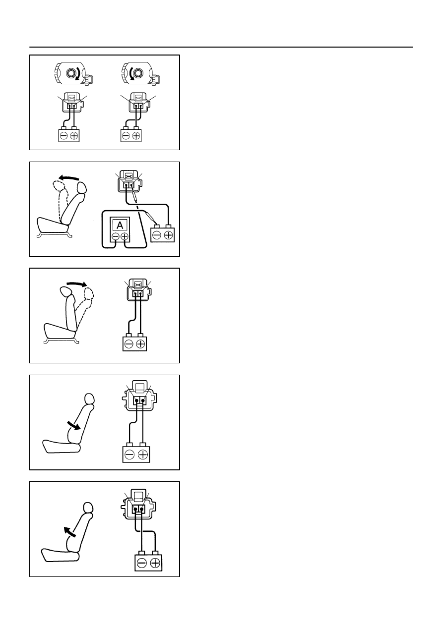
INSPECT RECLINING MOTOR OPERATION
(a)
Connect the positive (+) lead from the battery to terminal
1 and the negative (–) lead to terminal 2, check that the
motor turns clockwise.
(b)
Reverse the polarity, check that the motor turns counter-
clockwise.
If operation is not as specified, replace the seat adjuster.
11.
INSPECT RECLINING MOTOR PTC THERMISTOR OP-
ERATION
(a)
Connect the positive (+) lead from the battery to terminal
2, the positive (+) lead from the ammeter to terminal 1 and
the negative (–) lead to the battery negative (–) terminal,
then recline the seat back to the most forward position.
(b)
Continue to apply voltage, check that the current changes
to less than 1 ampere within 4 to 90 seconds.
(c)
Disconnect the leads from the terminals.
(d)
Approximately 60 seconds later, connect the positive (+)
lead from the battery to terminal 1 and the negative (–)
lead to terminal 2, check that the seat back begins to fall
backward.
If operation is not as specified, replace the seat adjuster.
12.
INSPECT LUMBAR SUPPORT MOTOR OPERATION
(a)
Connect the positive (+) lead from the battery to terminal
1 and the negative (–) lead to terminal 2, check that the
lumbar support moves to release side.
(b)
Reverse the polarity, check that the lumbar support
moves forward.
If operation is not as specified, replace the seat adjuster.
Нет комментариевНе стесняйтесь поделиться с нами вашим ценным мнением.
Текст