Toyota Sequoia (2005). Manual — part 577
DIDB3–01
–
DIAGNOSTICS
REAR SEAT ENTERTAINMANT SYSTEM
DI–2103
2297
DIAGNOSTIC TROUBLE CODE CHART
Terms
Meaning
Physical address
Three–digit code (shown in hexadecimal) which is given to each component com-
prising the AVC–LAN.
Corresponding to the function, individual symbols are specified.
Logical address
Two–digit code (shown in hexadecimal) which is given to each function comprising
the inner system of the AVC–LAN.
HINT:
DTC of the device which is directly connected via AVC–LAN, is displayed on the ”audio system or navigation
system” and the ”television display assy” respectively.
Titles for each unit are stated in the following order: parts name (physical address) [Name indicated by DTC]
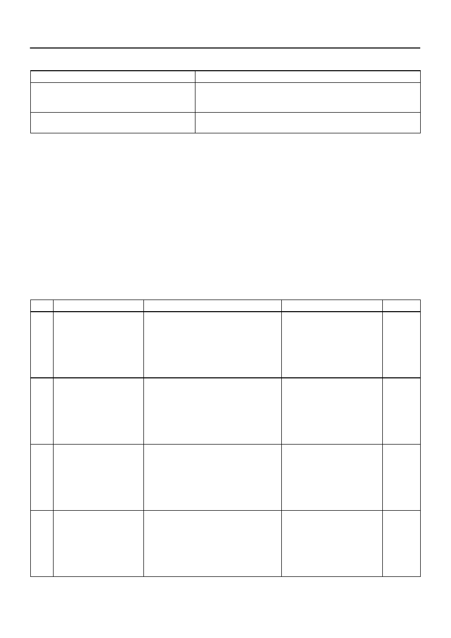
1.
MULTI–DISPLAY CONTROLLER SUB–ASSY (Physical address: 16C, 16D) [RSE–ECU]
HINT:
*1: Even if no failure is detected, this code may be stored depending on the battery condition or voltage
for starting the engine.
*2: This code is stored 180 seconds after the power supply connector is disconnected after engine
start.
*3: This code may be stored when the engine key is turned back to the ON position and then turned
again to the START position after engine start.
*4: This code may be stored when the engine key is turned back to the ON position and then turned
again to the START position in 1 minute after engine start.
(a)
Logical address: 01 (Communication control)
DTC
Name
Diagnosis
Verification
See page
D8
*2
No Response To Connection
Check
Component shown by sub–code is or had been
disconnected from system after engine start.
1. Power source circuit (Television
display assy).
2. Power source circuit (Disc play-
er controller).
3. AVC–LAN circuit.
4. Replace television display assy.
5. Replace disc player controller.
–
–
D9
*1
Last Mode Error
Component operated (sound and/or image was
provided) before engine stop is or was discon-
nected with ignition switch in the ACC or ON posi-
tion.
1. Power source circuit (Television
display assy).
2. Power source circuit (Disc play-
er controller).
3. AVC–LAN circuit
4. Replace television display assy.
5. Replace disc player controller.
–
–
DA
No Response to ON/OFF
Instruction
No response is identified when changing mode
(audio and visual mode change).
Detected when sound and picture do not change
by button operation.
1. Power source circuit (Television
display assy).
2. Power source circuit (Disc play-
er controller).
3. AVC–LAN circuit
4. Replace television display assy.
5. Replace disc player controller.
–
–
DB
*1
Mode Status Error
Dual alarm is detected.
1. Power source circuit (Television
display assy).
2. Power source circuit (Disc play-
er controller).
3. AVC–LAN circuit
4. Replace television display assy.
5. Replace disc player controller.
–
–

DI–2104
–
DIAGNOSTICS
REAR SEAT ENTERTAINMANT SYSTEM
2298
DC
*4
Transmission Error
Transmission to component shown by sub–code
failed.
(This code does not necessarily mean actual fail-
ure.)
If same sub–code is recorded in
other component(s), check harness
for power supply and communica-
tion system of all components
shown by code.
–
DE
*3
Slave Reset (Momentary Inter-
ruption)
After engine start, slave component has been dis-
connected.
1. Power source circuit (Television
display assy).
2. Power source circuit (Disc play-
er controller).
3. AVC–LAN circuit
4. Replace television display assy.
5. Replace disc player controller.
–
–
E4
*1
Multiple Frame Abort
Multiple frame transmission is aborted.
Since this DTC is provided for engi-
neering purpose, it may be detected
when no actual failure exists.
–
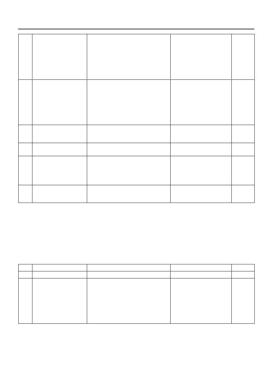
2.
Television display assy (Physical address: 1B0) [Rr–TV]
HINT:
*1: Even if no failure is detected, this code may be stored depending on the battery condition or voltage
for starting the engine.
*2: This code may be stored when the engine key is turned again in 1 minute after the engine start.
*3: This code may be stored when the engine key is turned again after the engine start.
*4: The code is stored 210 seconds after the power supply connector of the master component is dis-
connected with the ignition switch in the ACC or ON position.
(a)
Logical address: 01 (Communication control)
DTC
Name
Diagnosis
Verification
See page
22
RAM Error
Abnormal condition of RAM is detected.
Replace television display assy
–
D6
*1
Absence of Master
Component in which this code is recorded was
disconnected from system with the ignition switch
in the ACC or ON position. Or, when this code
was recorded, multi–display controller sub–assy
was disconnected.
1. Power source circuit (Television
display assy).
2. Power source circuit (Multi–dis-
play controller sub–assy).
3. AVC–LAN circuit.
4. Replace television display assy.
5. Replace Multi–display controller
sub–assy.
–
–
D7
*4
Communication Check Error
Component in which this code is recorded is or
was disconnected from system after engine start.
Or, when recording this code, multi–display con-
troller sub–assy was disconnected.
1. Power source circuit (Television
display assy).
2. Power source circuit (Multi–dis-
play controller sub–assy).
3. AVC–LAN circuit.
4. Replace television display assy.
5. Replace Multi–display controller
sub–assy.
–
–
DC
*2
Transmission Error
Transmission to component shown by sub–code
failed.
(Detecting this DTC does not necessarily mean
actual failure.)
If the same sub–code is recorded in
other components, check harness
for power supply and communica-
tion system of all components
shown by code.
–
–
DIAGNOSTICS
REAR SEAT ENTERTAINMANT SYSTEM
DI–2105
2299
DD
*3
Master Reset (Momentary Inter-
ruption)
After engine start, multi–display controller sub–
assy was disconnected from system.
1. Power source circuit (Television
display assy).
2. Power source circuit (Multi–dis-
play controller sub–assy).
3. AVC–LAN circuit.
4. Replace television display assy.
5. Replace Multi–display controller
sub–assy.
–
–
DF
*4
Master Error
Due to defective condition of component with a
display, master function is switched to audio
equipment.
Error occurs in communication between sub–
master (audio) and master component.
1. Power source circuit (Television
display assy).
2. Power source circuit (Multi–dis-
play controller sub–assy).
3. AVC–LAN circuit.
4. Replace television display assy.
5. Replace Multi–display controller
sub–assy.
–
–
E0
*1
Registration Completion
Instruction Error
”Registration Completion Instruction” command
from master cannot be received.
Since this DTC is provided for engi-
neering purposes, it may be de-
tected when no actual failure exists.
–
E2
ON/OFF Instruction Parameter
Error
Error occurs in ON/OFF controlling command
from multi–display controller sub–assy.
Replace multi–display controller
sub–assy.
–
E3
*1
Registration Request Transmis-
sion
Registration Request command is output from
slave component.
Registration Connection Check Instruction, Reg-
istration Request command is output from sub–
master component.
Since this DTC is provided for engi-
neering purposes, it may be de-
tected when no actual failure exists.
–
E4
*1
Multiple Frame Abort
Multiple frame transmission is aborted.
Since this DTC is provided for engi-
neering purposes, it may be de-
tected when no actual failure exists.
–
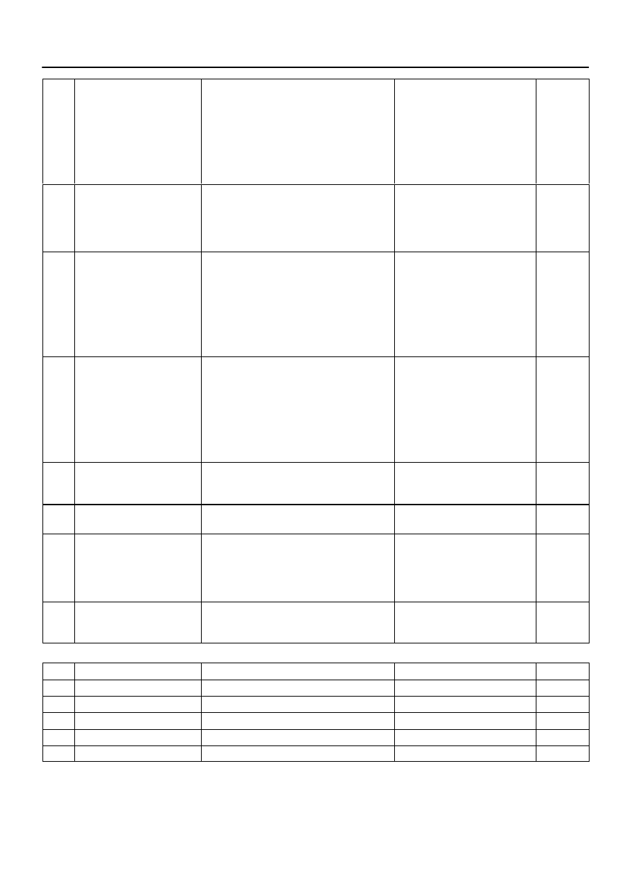
3.
Disc player controller (Physical address: 1A0) [DVD–P]
HINT:
*1: Even if no failure is detected, this code may be stored depending on the battery condition or voltage
for starting an engine.
*2: This code may be stored when the engine key is turned again 1 min. after the engine starts.
*3: This code may be stored when the engine key is turned again after the engine starts.
*4: When 210 sec. have passed after pulling out the power supply connector of the master component
with the ignition switch in ACC or ON, this code is stored.
(a)
Logical address: 01 (Communication control)
DTC
Name
Diagnosis
Verification
See page
22
RAM Error
Abnormal condition of RAM is detected.
Replace disc player controller
–
D6
*1
Absence of Master
Component in which this code is recorded was
disconnected from system with the ignition switch
in the ACC or ON position. Or, when this code
was recorded, multi–display controller sub–assy
was disconnected.
1. Power source circuit (Disc play-
er controller).
2. Power source circuit (Multi–dis-
play controller sub–assy).
3. AVC–LAN circuit.
4. Replace disc player controller.
5. Replace Multi–display controller
sub–assy.
–
–
DI–2106
–
DIAGNOSTICS
REAR SEAT ENTERTAINMANT SYSTEM
2300
D7
Communication Check Error
Component in which this code is recorded is or
was disconnected from system after engine start.
Or, when recording this code, multi–display con-
troller sub–assy was disconnected.
1. Power source circuit (Disc play-
er controller).
2. Power source circuit (Multi–dis-
play controller sub–assy).
3. AVC–LAN circuit.
4. Replace disc player controller.
5. Replace Multi–display controller
sub–assy.
–
–
DC
*2
Transmission Error
Transmission to component shown by sub–code
has been failed.
(Detecting this DTC does not necessarily mean
actual failure.)
If same sub–code is recorded in
other components, check harness
for power supply and communica-
tion system of all components
shown by code
–
DD
*3
Master Reset (Momentary Inter-
ruption)
After engine start, radio and player assembly was
disconnected from system.
1. Power source circuit (Disc play-
er controller).
2. Power source circuit (Multi–dis-
play controller sub–assy).
3. AVC–LAN circuit.
4. Replace disc player controller.
5. Replace Multi–display controller
sub–assy.
–
–
DF
*4
Master Error
Due to defective condition of component with a
display, master function is switched to audio
equipment.
Error occurs in communication between sub–
master (audio) and master component.
1. Power source circuit (Disc play-
er controller).
2. Power source circuit (Multi–dis-
play controller sub–assy).
3. AVC–LAN circuit.
4. Replace disc player controller.
5. Replace Multi–display controller
sub–assy.
–
–
E0
*1
Registration Completion
Instruction Error
”Registration Completion Instruction” command
from master cannot be received.
Since this DTC is provided for engi-
neering purpose, it may be detected
when no actual failure exists
–
E2
ON/OFF Instruction Parameter
Error
Error occurs in ON/OFF controlling command
from disc player controller.
Replace disc player controller
–
E3
*1
Registration Request Transmis-
sion
Registration Request command is output from
slave component.
Registration Connection Check Instruction, Reg-
istration Request command is output from sub–
master component.
Since this DTC is provided for engi-
neering purpose, it may be detected
when no actual failure exists
–
E4
*1
Multiple Frame Abort
Multiple frame transmission is aborted.
Since this DTC is provided for engi-
neering purpose, it may be detected
when no actual failure exists
–
(b)
Logical address: 44 (DVD)
DTC
Name
Diagnosis
Verification
See page
42
No Disc Readout
Disc cannot be read.
Inspect disc
–
44
DVD Error
Error is detected in disc player controller.
Replace disc player controller
–
45
EJECT Error
Disc cannot be ejected.
Replace disc player controller
–
46
Disc Crack
A crack and dirt are in a disc.
Replace disc player controller
–
52
Player Error
Clamp unusually generating.
Replace disc player controller
–
Нет комментариевНе стесняйтесь поделиться с нами вашим ценным мнением.
Текст