Toyota Sequoia (2005). Manual — part 628
DIDKP–01
I15876
I21
I20
I19
I22
–
DIAGNOSTICS
AIR CONDITIONING SYSTEM
DI–2307
2501
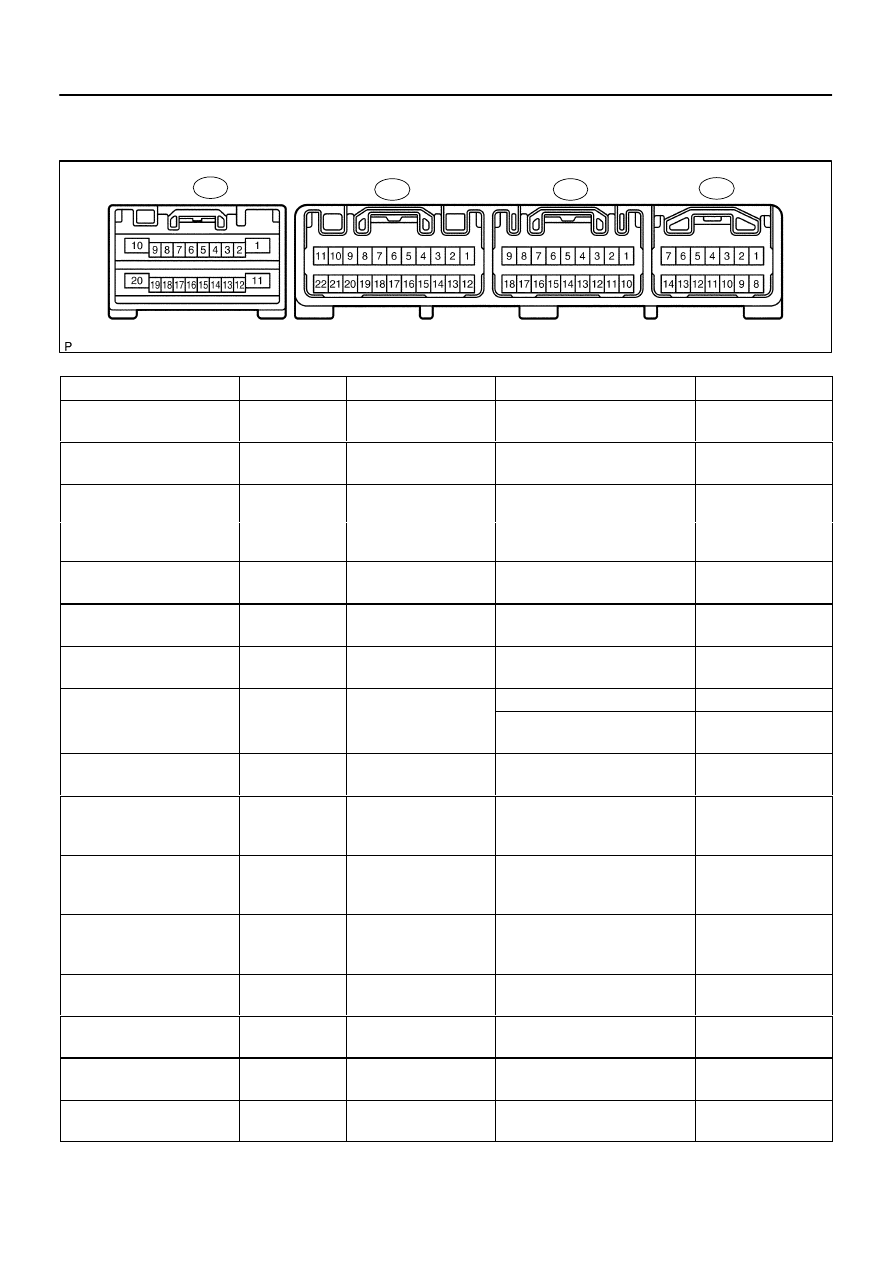
TERMINALS OF ECU
Integration Control and Panel
Symbols (Terminals No.)
Wiring Color
Terminal Description
Condition
Specified Condition
+B
↔
GND
(I19–1
↔
I19–10)
R
↔
O
Power source (Back–up)
Always
10 to 14 V
IG+
↔
GND
(I19–2
↔
I19–10)
R–L
↔
O
Power source (IG)
IG switch OFF
→
ON
10 to 14 V
PSW
↔
GND
L B
O
P
it h i
l
A/C refrigerant pressure: less than
0.19 MPa (2.0 kgf/cm
2
)
10 t 14
B l
1 0 V
PSW
↔
GND
(I19–6
↔
I19–10)
L–B
↔
O
Pressure switch signal
0.19 MPa (2.0 kgf/cm )
or more than 3.14 MPa (32
Kgf/cm
2
)
10 to 14
→
Below 1.0 V
HR
↔
GND
(I22–6
↔
I19–10)
L–Y
↔
O
Blower motor operation
signal
Blower fan OFF
→
ON
10 to 14
→
Below 1.0 V
GND
↔
Body ground
(I19–10
↔
Body ground)
*1
O
↔
Body ground
Ground for main power
supply
Constant
Continuity
ACC
↔
GND
(I19–11
↔
I19–10)
P
↔
O
Power source (ACC)
Turn ignition switch ACC
10 to 14 V
TAM
SG TAM
A bi
t t
t
IG ON, Ambient temp.: 25
°
C (77
°
F)
1.3 to 1.8 V
TAM
↔
SG–TAM
(I19–8
↔
I19–20)
LG–B
↔
Y–B
Ambient temperature sen-
sor signal
IG ON, Ambient temp.: 40
°
C
(104
°
F)
0.8 to 1.3 V
BLW
↔
GND
G B
O
Blower motor operation
Bl
f
OFF
ON
10 t 14
B l
1 0 V
BLW
↔
GND
(I19–4
↔
I19–10)
G–B
↔
O
Blower motor o eration
signal
Blower fan OFF
→
ON
10 to 14
→
Below 1.0 V
RrCLK (I21–15)
*1
B
Communication signal
Communication circuit
(Built in Fr A/C control panel
→
Rr
A/C control panel)
–
RrDPD (I21–5)
*1
R
Communication signal
Communication circuit
(Built in Fr A/C control panel
→
Rr
A/C control panel)
–
RrSWD (I21–6)
*1
W
Communication signal
Communication circuit
(Built in Fr A/C control panel
→
Rr
A/C control panel)
–
RrAMH
↔
GND
(I21–8
↔
I19–10)
*1
R–G
↔
O
Rear air mix control ser-
vomotor operation signal
Rr temp. control switch: Max.
COOL
→
Max. HOT
Below 1.0
→
10 to 14 V for 16 sec.
RrAMC
↔
GND
(I21–9
↔
I19–10)
*1
L–B
↔
O
Rear air mix control ser-
vomotor operation signal
Rr temp. control switch: Max. HOT
→
Max. COOL
Below 1.0
→
10 to 14 V for 16 sec.
RrSG
↔
GND
(I21–10
↔
I19–10)
*1
L–R
↔
O
Ground for rear evapora-
tor temperature sensor
Constant
Continuity
RrS5
↔
RrSG
(I22–4
↔
I21–10)
*1
L–Y
↔
L–R
Power supply for rear air
mix control servomotor
IG ON
4.5 to 5.5 V
DI–2308
–
DIAGNOSTICS
AIR CONDITIONING SYSTEM
2502
Symbols (Terminals No.)
Wiring Color
Terminal Description
Condition
Specified Condition
RrTP
↔
RrSG
(I21–18
↔
I21–10)
*1
W
↔
L–R
Rear air mix damper posi-
tion
sensor signal
Rr temp. control switch: Max.
COOL
→
Max. HOT
4.0 to 1.0 V
AC1
↔
GND
(I22–4
↔
I19–10)
G – B
↔
O
Compressor operation
signal
IG ON, A/C switch: OFF
→
ON
3.7 to 4.5
→
1.3 to 2.6 V
RrFACE2
↔
GND
(I21–11
↔
I19–10)
*1
P–B
↔
O
Rear air outlet control ser-
vomotor operation signal
Rr A/C control panel switch: except
FACE
→
FACE
10 to 14
→
Below 1.0 V
RrBLK (I21–4)
*1
LG–B
Communication signal
Communication circuit
(Built in Fr. A/C control panel
→
Rr.
A/C control panel)
–
RrSTX (I21–14)
*1
G–Y
Communication signal
Communication circuit
(Built in Fr. A/C control panel
→
Rr.
A/C control panel)
–
RrVM
↔
GND
(I21–7
↔
I19–10)
*1
W–G
↔
O
Rear blower motor control
signal
Rr blower control switch: LO
→
MID
→
HI
7.2
→
4.2
→
0.5 V
RrHR
↔
GND
(I22–7
↔
I19–10)
*1
L–O
↔
O
Rear blower motor opera-
tion signal
Rr blower control switch: OFF
→
LO
10 to 14
→
Below 1.0 V
RrBLW
↔
GND
(I21–16
↔
I19–10)
*1
L
↔
O
Rear blower motor opera-
tion signal
Rr blower control switch: OFF
→
LO
Below 1.0
→
1.5 to 3.0 V
RrFACE
↔
GND
(I21–2
↔
I19–10)
*1
Y–B
↔
O
Rear air outlet control ser-
vomotor control signal
Rr A/C control panel FACE switch:
OFF
→
ON
10 to 14
→
Below 1.0 V while
switch is pushed
RrB/L
↔
GND
(I21–3
↔
I19–10)
*1
BR–W
↔
O
Rear air outlet control ser-
vomotor control signal
Rr A/C control panel B/L switch:
OFF
→
ON
10 to 14
→
Below 1.0 V while
switch is pushed
RrFOOT
↔
GND
(I21–13
↔
I19–10)
*1
G–R
↔
O
Rear air outlet control ser-
vomotor control signal
Rr A/C control panel FOOT switch:
OFF
→
ON
10 to 14
→
Below 1.0 V while
switch is pushed
RrTE
↔
RrSG
LG R
L R
Rear evaporator tempera-
Rr evaporator temp.: 0
°
C (32
°
F)
2.0 to 2.4 V
RrTE
↔
RrSG
(I21–17
↔
I21–10)
*1
LG–R
↔
L–R
Rear eva orator tem era
ture sensor signal
Rr evaporator temp.: 15
°
C (59
°
F)
2.0 to 2.4 V
RrB/L2
↔
GND
(I21–12
↔
I19–10)
*1
P–G
↔
O
Rear air outlet control ser-
vomotor control signal
Rr A/C control panel switch: except
B/L
→
B/L
10 to 14
→
Below 1.0 V
FOOT
↔
GND
(I21–17
↔
I19–10)
Y–B
↔
O
Air outlet control servo-
motor control signal
Mode control switch except: FOOT
→
FOOT
10 to 14
→
Below 1.0 V
FDEF
↔
GND
(I20–7
↔
I19–10)
LG–R
↔
O
Air outlet control servo-
motor control signal
Mode control switch except: FOOT/
DEF
→
FOOT/DEF
10 to 14
→
Below 1.0 V
DEF
↔
GND
(I20–18
↔
I19–10)
B–W
↔
O
Air outlet control servo-
motor control signal
Mode control switch except: DEF
→
DEF
10 to 14
→
Below 1.0 V
AMH
↔
GND
R L
O
Air mix control servomotor
IG ON, Set temp.: Max. Cool
Below 1.0 V
AMH
↔
GND
(I20–10
↔
I19–10)
R–L
↔
O
Air mix control servomotor
operation signal
IG ON, Set temp.: Max. Hot
10 to 14 V
S5–AM
↔
SG–TP
(I20–22
↔
I20–12)
R–Y
↔
L–R
Power supply for air mix
control servomotor
IG ON
4.5 to 5.5 V
TP
↔
SG–TP
G R
L R
Air mix damper position
IG ON, Set temp.: Max. Cool
3.5 to 4.5 V
TP
↔
SG TP
(I20–15
↔
I20–12)
G–R
↔
L–R
Air mix dam er osition
sensor signal
IG ON, Set temp.: Max. Hot
0.5 to 1.5 V
AMC
↔
GND
W L
O
Air mix control servomotor
IG ON, Set temp.: Max. Cool
10 to 14 V
AMC
↔
GND
(I20–9
↔
I19–10)
W–L
↔
O
Air mix control servomotor
control signal
IG ON, Set temp.: Max. Hot
Below 1.0 V
S5–AI
↔
SG–TPI
(I20–11
↔
I20–13)
L–B
↔
Y–R
Air inlet control servomo-
tor control signal
IG ON
4.5 to 5.5 V
TR
↔
SG–TR
L W
R W
Room temperature sensor
IG ON, Cabin temp.: 25
°
C (77
°
F)
1.8 to 2.2 V
TR
↔
SG TR
(I20–3
↔
I20–1)
L–W
↔
R–W
Room tem erature sensor
signal
IG ON, Cabin temp.: 40
°
C (104
°
F)
1.2 to 1.6 V
–
DIAGNOSTICS
AIR CONDITIONING SYSTEM
DI–2309
2503
Symbols (Terminals No.)
Wiring Color
Terminal Description
Condition
Specified Condition
TS
↔
S5–TS
LG
B
S l
i
l
IG ON
0 8 t 4 3 V
TS
↔
S5 TS
(I20–14
↔
I20–21)
LG
↔
B
Solar sensor signal
IG ON
0.8 to 4.3 V
AIR
↔
GND
G W
O
Air inlet control servomo-
IG ON, Push FRS switch
Below 1.0 V
AIR
↔
GND
(I20–20
↔
I19–10)
G–W
↔
O
Air inlet control servomo
tor operation signal
IG ON, Push REC switch
10 to 14 V
AIF
↔
GND
R
O
Air inlet control servomo-
IG ON, Push FRS switch
10 to 14 V
AIF
↔
GND
(I20–8
↔
I19–10)
R
↔
O
Air inlet control servomo
tor operation signal
IG ON, Push REC switch
Below 1.0 V
TPI
↔
SG–TPI
W
Y R
Air inlet control servomo-
IG ON, Push REC switch
3.5 to 4.5 V
TPI
↔
SG TPI
(I20–16
↔
I20–13)
W
↔
Y–R
Air inlet control servomo
tor control signal
IG ON, Push FRS switch
0.5 to 1.5 V
R TR
SG R TR
R
t
t
IG ON, Rr room temp.: 25
°
C (77
°
F)
1.8 to 2.2 V
RrTR
↔
SG–RrTR
(I22–13
↔
I22–14)
*1
GR–R
↔
R–Y
Rear room temperature
sensor signal
IG ON, Rr room temp.: 40
°
C
(104
°
F)
1.2 to 1.6 V
FACE
↔
GND
(I20–5
↔
I19–10)
GR
↔
O
Air outlet control servo-
motor control signal
Mode control switch: except FACE
→
FACE
10 to 14
→
Below 1.0 V
B/L
↔
GND
(I20–6
↔
I19–10)
BR–W
↔
O
Air outlet control servo-
motor control signal
Mode control switch: except BI–
LEVEL
→
BI–LEVEL
10 to 14
→
Below 1.0 V
IGN
↔
GND
Y G
O
E
i
l ti
i
l
E
i
idli
P l
ti
IGN
↔
GND
(I22–3
↔
I19–10)
Y–G
↔
O
Engine revolution signal
Engine idling
Pulse generation
TW
↔
GND
W R
O
Engine coolant tempera-
IG ON
P l
ti
TW
↔
GND
(I22–2
↔
I19–10)
W–R
↔
O
Engine coolant tem era
ture sensor signal
IG ON
Pulse generation
ACT
↔
GND
(I22–5
↔
I19–10)
LG–B
↔
O
Compressor operation
signal
IG ON, A/C switch: OFF
→
ON
Below 1.0
→
10 to 14 V
TE
↔
SG–TE
G B
W G
Evaporator temperature
IG ON, Evaporator temp.: 0
°
C
(32
°
F)
2.0 to 2.4 V
TE
↔
SG TE
(I20–4
↔
I20–2)
G–B
↔
W–G
Eva orator tem erature
sensor signal
IG ON, Evaporator temp.: 15
°
C
(59
°
F)
1.4 to 1.8 V
MGC
↔
GND
(I19–5
↔
I19–10)
L
↔
O
Magnetic clutch control
signal
Engine start
A/C switch: OFF
→
ON
10 to 14
→
Below 1.0 V
LOCK
↔
GND
(I19–9
↔
I19–10)
W–R
↔
O
Compressor lock sensor
signal
Engine start
A/C switch: OFF
→
ON
Pulse generation
*1: w/ Rear A/C
DIDKQ–01
D05981
DLC3
I15897
Trouble Code Display
I15897
DEF. SW
DI–2310
–
DIAGNOSTICS
AIR CONDITIONING SYSTEM
2504
DTC CHECK / CLEAR
1.
DTC CHECK USING HAND–HELD TESTER
(a)
Hook up the hand–held tester to the DLC3.
(b)
Turn the ignition switch to the ON position.
(c)
Read the DTCs following the prompts on the tester
screen.
Refer to the hand–held tester operator’s manual for fur-
ther details.
(d)
Clear the DTCs.
HINT:
After repairing the malfunctions, clear the DTCs.
(1)
Connect the hand–held tester to the DLC3.
(2)
Turn the ignition switch to the ON position.
(3)
Erase the DTCs following the prompts on the tester
screen.
HINT:
Refer to the hand–held tester operator’s manual for further de-
tails.
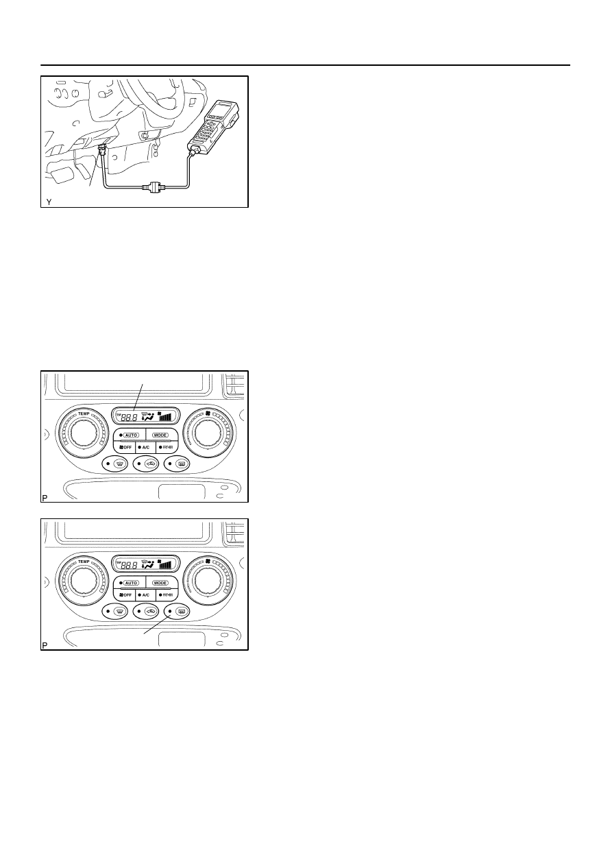
2.
DTC CHECK (SENSOR CHECK)
(a)
Perform an indicator check. After the indicator check is
completed, the system enters the DTC check mode auto-
matically (See page
).
(b)
Read the DTC displayed on the panel. Refer to the list of
DTCs on page
are output on the temperature display.).
If the slower display is desired, press the DEF. SW and
change it to step operation. Each time the Temp. Control
switch is pressed, the display changes by 1 step.
Нет комментариевНе стесняйтесь поделиться с нами вашим ценным мнением.
Текст