Toyota Sequoia (2005). Manual — part 524
I03343
I03344
I03345
I03977
ECU
ECU
ECU
ECU
ECU
ECU
Open
Open
ECU
ECU
Open
ECU
Disconnection (DTC is detected)
Open (DTC is detected)
Open (DTC is not detected)
I03346
Body ECU
Open
Open
Detects the DTCs for the
communication stop of the
3 ECUs.
Example
–
DIAGNOSTICS
MULTIPLEX COMMUNICATION SYSTEM
DI–1891
2085
3.
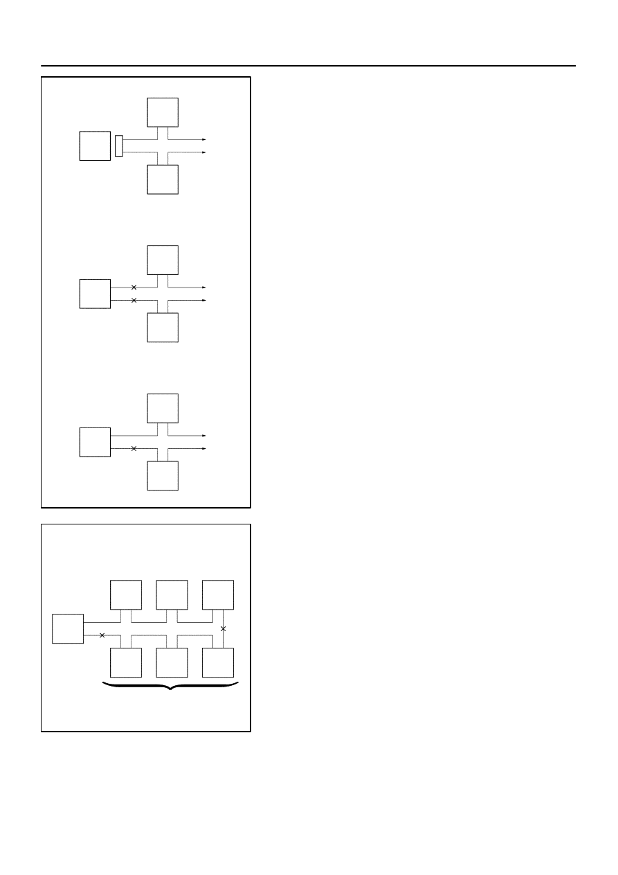
DIAGNOSIS SYSTEM
(a)
If a DTC for an ECU communication stop is indicated, a
connector may be disconnected or there may be open cir-
cuits on 2 or more communication buses. When there is
an open circuit on only 1 communication bus, no DTC will
be detected.
(b)
If 2 communication buses are open at the position shown
in the illustration, DTCs for the ECU communication stop
between these 2 buses are indicated.
DI3IO–11
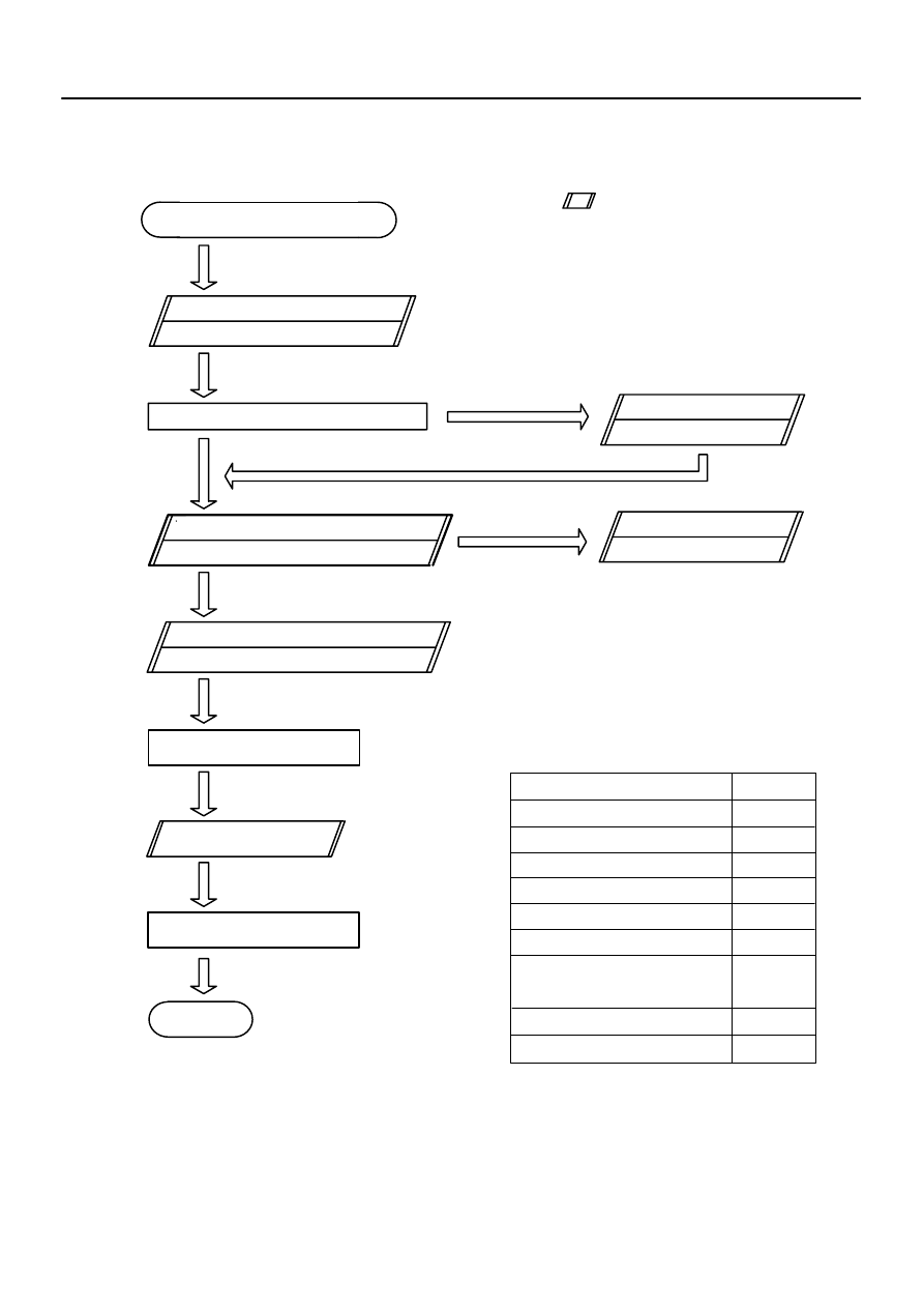
Customer Problem Analysis
Vehicle Brought to Workshop
Problem Symptom Confirmation
Symptom Simulation
Problem does not
occur
Check DTC
Normal code
Problem Symptoms Table
Identification of Problem
Repair
Confirmation Test
End
Titles inside
are titles of pages in this
manual, with the page number indicated in
the bottom portion. See the indicated pages
for detailed explanations.
1
2
3
4
6
8
P.
*1
P.
P.
Malfunction code
Problem
occurs
Circuit Inspection
See page
Body control system
Driver door control system
Passenger door control system
System
Step 4, 8: Diagnostic steps permitting the use of the hand–held tester.
*1
5
7
Combination meter system
Slide roof control system
Back door control system
Power seat control system
w/ Driving position memory
Supplemental restraint system
Air conditioning system
DI–1892
–
DIAGNOSTICS
MULTIPLEX COMMUNICATION SYSTEM
2086
HOW TO PROCEED WITH TROUBLESHOOTING
Perform troubleshooting in accordance with the procedure on the following page.
DI3IP–10
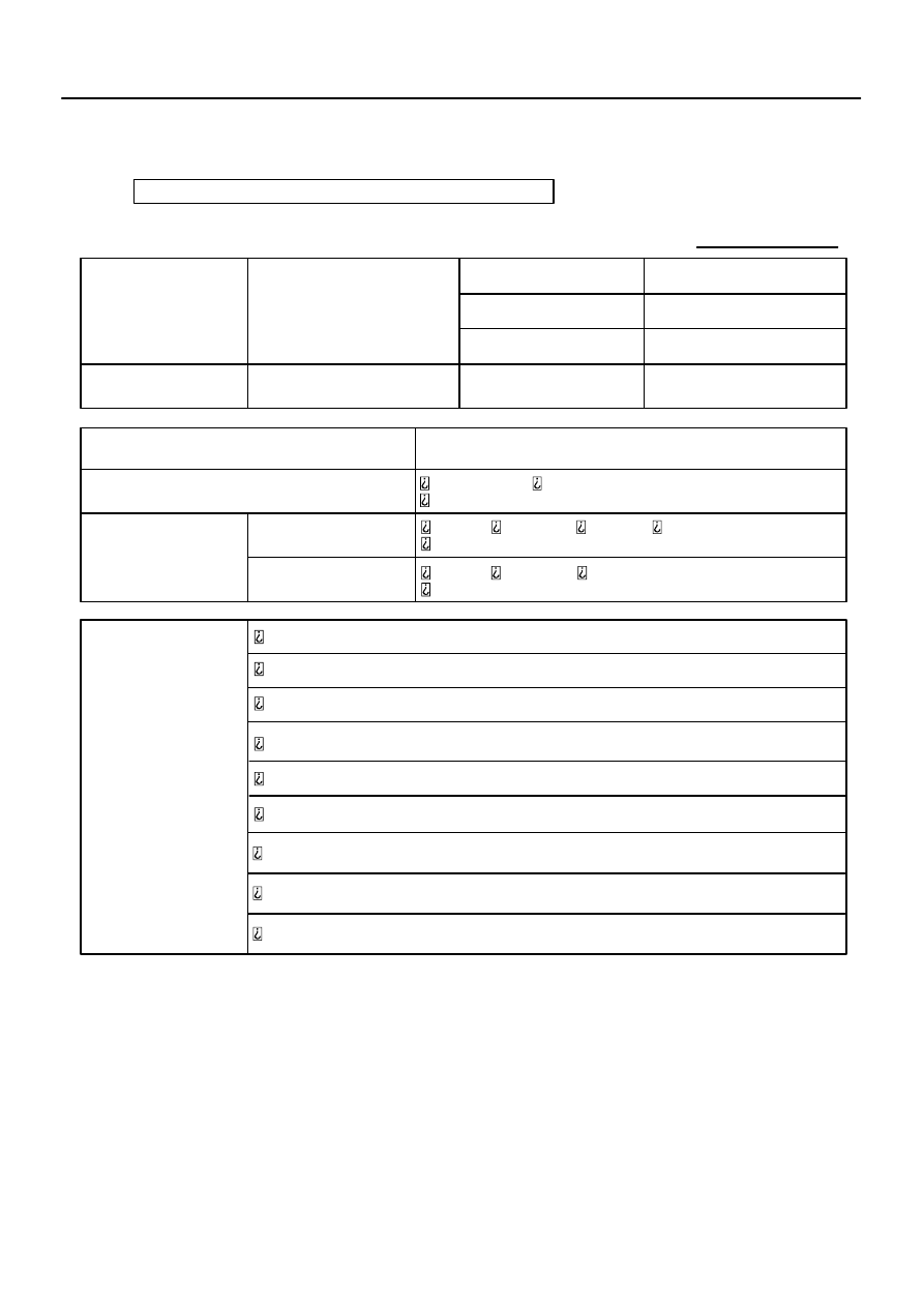
MULTIPLEX COMMUNICATION SYSTEM Check Sheet
Inspector’s name:
Customer’s Name
VIN
Production Date
Licence Plate No.
Odometer Reading
/ /
km
mile
Weather Conditions
When Problem
Occurred
Frequency Problem Occurs
Weather
/ /
Once only
Brought in
Malfunction
System
Outdoor Temperature
Fine
Cloudy
Rainy
Snowy
Various/Others
Hot
Warm Cool
Cold (Approx.
°
F (
°
C))
Constant Sometimes ( times per day, month)
Driver Door Control System
Passenger Door Control System
Combination Meter System
Body Control System
Back Door Control System
Slide Roof Control System
Power Seat Control System (w/ Driving Position Memory)
Supplemental Restraint System
Air Condition System
–
DIAGNOSTICS
MULTIPLEX COMMUNICATION SYSTEM
DI–1893
2087
CUSTOMER PROBLEM ANALYSIS CHECK
DIDFA–01
I27698
B5
B6
B7
DI–1894
–
DIAGNOSTICS
MULTIPLEX COMMUNICATION SYSTEM
2088
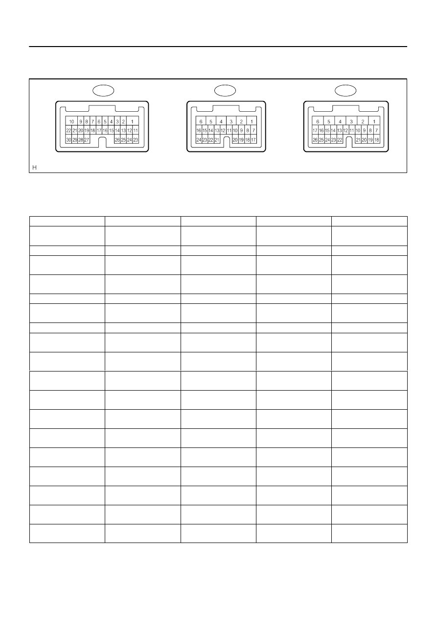
TERMINALS OF ECU
1.
CHECK BODY ECU
(a)
Disconnect the B5, B6 and B7 ECU connectors.
(b)
Measure the resistance or voltage of each terminal of the wire harness side connector.
Standard:
Symbols (Terminal No.)
Wiring Color
Terminal Description
Condition
Specified Condition
BDR (B6–2) –
Body ground
L–W – Body ground
+B (BATT) power supply
Always
10 to 14 V
IG (B7–6) – Body ground
B–R – Body ground
Ignition power supply
Ignition switch ON
10 to 14 V
ACC (B7–10) –
Body ground
GR – Body ground
ACC power supply
Ignition switch ACC
10 to 14 V
OBD2 (B5–2) –
Body ground
G–R – Body ground
Bus ”+” line
During transmission
Pulse generation
S+B (B6–1) – Body ground
W–L – Body ground
+B (BATT) power supply
Always
10 to 14 V
BECU (B6–5) –
Body ground
W–R – Body ground
+B (BATT) power supply
Always
10 to 14 V
WIG (B7–5) – Body ground
L–Y – Body ground
Ignition power supply
Ignition switch ON
10 to 14 V
MPX3 (B7–20) –
Body ground
G–O – Body ground
MPX line
Always
10 k
Ω
or higher
MPX2 (B5–24) –
Body ground
L–Y – Body ground
MPX line
Always
10 k
Ω
or higher
MPX1 (B7–22) –
Body ground
W–L – Body ground
MPX line
Always
10 k
Ω
or higher
GND1 (B6–6) –
Body ground
W–B – Body ground
Ground
Always
Below 1
Ω
PRG – GND1
(B5–5 – B6–6)
V – W–B
Wireless transmitter signal
ground
Wireless door look receiver
communication circuit
–
RDA – GND1
(B5–4 – B6–6)
R–G – W–B
Wireless transmitter signal
input
Wireless door lock control
system is operated
Below 1 V
RDA – GND1
(B5–4 – B6–6)
R–G – W–B
Wireless transmitter signal
input
Wireless door lock control
system is not operated
10 to 14 V
GSW
(B6–16)
GR–R
Air bag sensor commu-
nication signal
Air bag sensor commu-
nication circuit
–
CLTS (*1) – GND1
(B6–12 – B6–6)
Y – W–B
Automatic light control sen-
sor (Signal)
Ignition switch OFF
Below 1 V
CLTS (*1) – GND1
(B6–12 – B6–6)
Y – W–B
Automatic light control sen-
sor (Signal)
Ignition switch ON
Signal waveform
CLTE (*1) – GND1
(B6–3 – B6–6)
BR – W–B
Automatic light control sen-
sor (Ground)
Always
Below 1 V
Нет комментариевНе стесняйтесь поделиться с нами вашим ценным мнением.
Текст