Toyota Sequoia (2005). Manual — part 344
H02750
Airbag Sensor Assembly
A20 +SL
30
IA3
1
IA3
2
A20
28
A11
Front Airbag Sensor LH
2
1
–SL
W
W
B
B
+SL
–SL
–
DIAGNOSTICS
SUPPLEMENTAL RESTRAINT SYSTEM
DI–1171
1365
DTC
B1615/14 Front Airbag Sensor LH Malfunction
CIRCUIT DESCRIPTION
The front airbag sensor LH consists of the diagnosis circuit, the frontal deceleration sensor, etc.
If the airbag sensor assembly receives signals from the frontal deceleration sensor, it determines whether
or not the SRS should be activated.
DTC B1615/14 is recorded when a malfunction is detected in the front airbag sensor LH circuit.
DTC No.
DTC Detection Condition
Trouble Area
B1615/14
The airbag sensor assembly receives a line short circuit
signal, an open circuit signal, a short circuit to ground sig-
nal or a short circuit to B+ signal in the front airbag sensor
LH circuit for 2 seconds.
Front airbag sensor LH malfunction
Airbag sensor assembly malfunction
Front airbag sensor LH
Airbag sensor assembly
Cowl wire
Engine room main wire
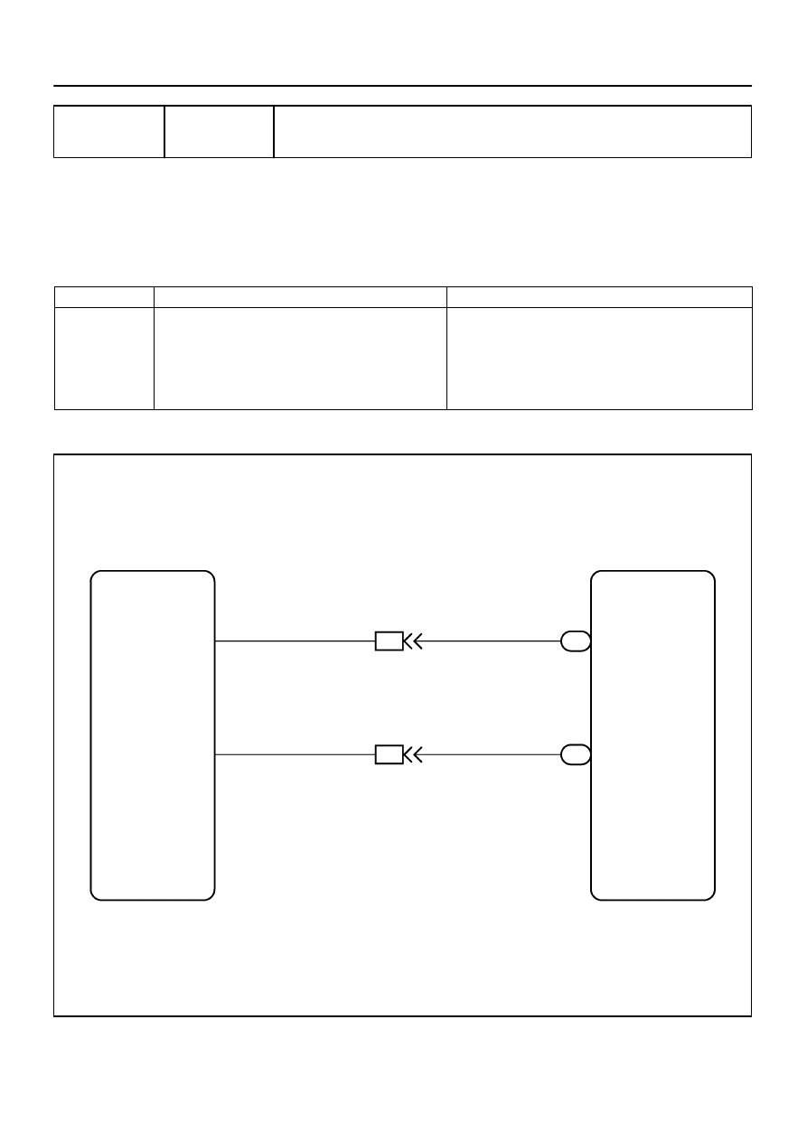
WIRING DIAGRAM
DIDGT–01
H10600
H02757
W02044
H23570
CG
TC
DTC B1615/14
DLC3
Front Airbag
Sensor LH
Airbag
Sensor
Assembly
DI–1172
–
DIAGNOSTICS
SUPPLEMENTAL RESTRAINT SYSTEM
1366
INSPECTION PROCEDURE
CAUTION:
Be sure to perform the following procedures before troubleshooting to avoid unexpected airbag de-
ployment.
(a)
Turn the ignition switch to the LOCK position.
(b)
Disconnect the negative (–) terminal cable from the battery, and wait for at least 90 seconds.
(c)
Disconnect the connectors from the airbag sensor assembly.
(d)
Disconnect the connectors from the steering wheel pad.
(e)
Disconnect the connectors from the front passenger airbag assembly.
(f)
w/ Side and curtain shield airbag:
Disconnect the connectors from the side airbag assembly LH and RH.
(g)
w/ Side and curtain shield airbag:
Disconnect the connectors from the curtain shield airbag assembly LH and RH.
(h)
Disconnect the connectors from the front seat outer belt LH and RH.
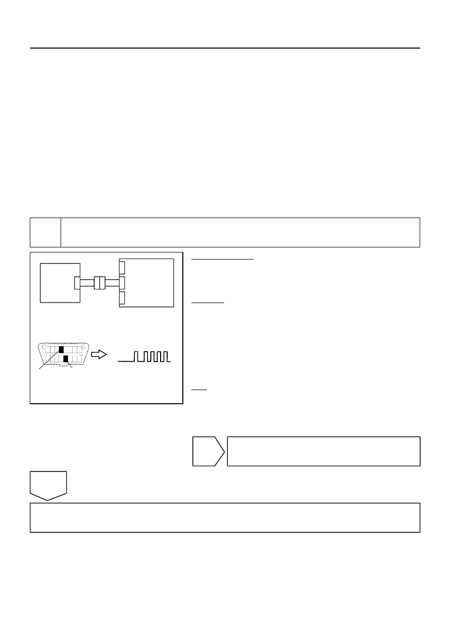
1
Check DTC.
PREPARATION:
(a)
Connect the connectors to the airbag sensor assembly.
(b)
Connect the negative (–) terminal cable to the battery,
and wait for at least 2 seconds.
CHECK:
(a)
Turn the ignition switch to the ON position, and wait for at
least 60 seconds.
(b)
Clear the DTCs stored in memory (see page
(c)
Turn the ignition switch to the LOCK position.
(d)
Turn the ignition switch to the ON position, and wait for at
least 60 seconds.
(e)
OK:
DTC B1615/14 is not output.
HINT:
Codes other than DTC B1615/14 may be output at this time, but
they are not related to this check.
NG
Go to step 2.
OK
From the results of the above inspection, the malfunctioning part can now be considered normal.
To make sure of this, use the simulation method to check (see page
H03353
H08016 G27651
H23623
Front Airbag
Sensor LH
Airbag
Sensor
Assembly
+SL
–SL
A
B
D
F
E
C
C
Service Wire
+SL
–SL
A20
A11
–
DIAGNOSTICS
SUPPLEMENTAL RESTRAINT SYSTEM
DI–1173
1367
2
Check connection of connectors.
PREPARATION:
(a)
Turn the ignition switch to the LOCK position.
(b)
Disconnect the negative (–) terminal cable from the battery, and wait for at least 90 seconds.
CHECK:
Check that the connectors are properly connected to the airbag sensor assembly and the front airbag sensor
LH.
OK:
The connectors are connected securely.
NG
Connect connectors, then go to step 1.
OK
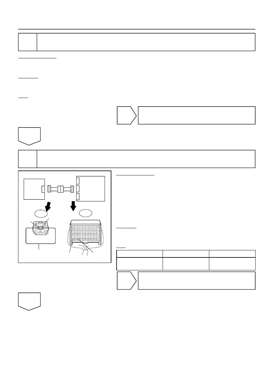
3
Check front airbag sensor LH circuit (open).
PREPARATION:
(a)
Disconnect the connectors from the airbag sensor as-
sembly and the front airbag sensor LH.
(b)
Using a service wire, connect A11–2 (+SL) and A11–1
(–SL) of connector ”E”.
NOTICE:
Do not forcibly insert a service wire into the terminals of the
connector when connecting.
CHECK:
Measure the resistance according to the value(s) in the table
below.
OK:
Tester Connection
Condition
Specified Condition
A20–30 (+SL) –
A20–28 (–SL)
Always
Below 1
Ω
NG
Go to step 8.
OK
H03355
G27651
H23624
Front Airbag
Sensor LH
Airbag
Sensor
Assembly
–SL
+SL
A
B
D
E
F
C
A20
H03355
G27651
H23624
Front Airbag
Sensor LH
Airbag
Sensor
Assembly
–SL
+SL
A
B
D
E
F
C
A20
DI–1174
–
DIAGNOSTICS
SUPPLEMENTAL RESTRAINT SYSTEM
1368
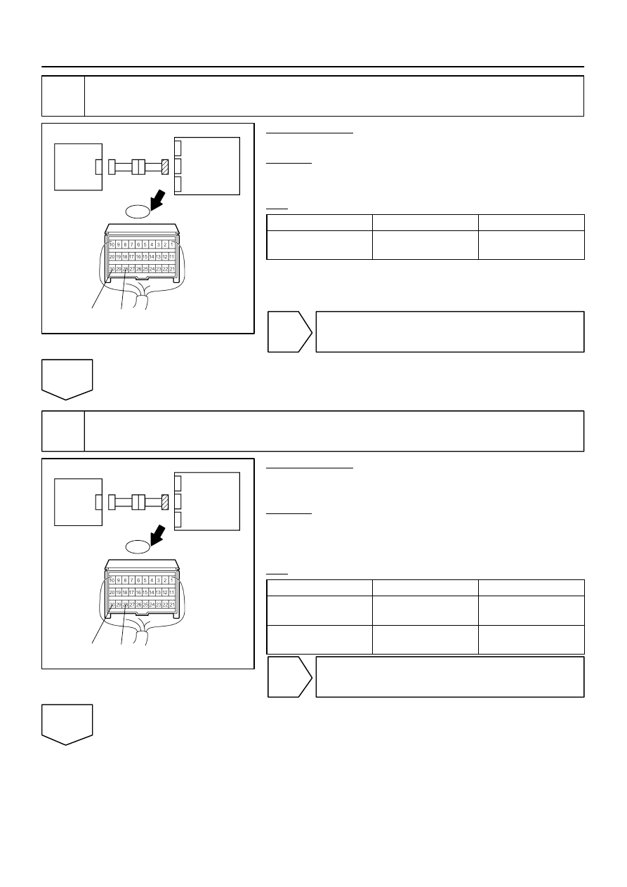
4
Check front airbag sensor LH circuit (short).
PREPARATION:
Disconnect the service wire from connector ”E”.
CHECK:
Measure the resistance according to the value(s) in the table
below.
OK:
Tester Connection
Condition
Specified Condition
A20–30 (+SL) –
A20–28 (–SL)
Always
1 M
Ω
or higher
NG
Go to step 9.
OK
5
Check front airbag sensor LH circuit (short to B+).
PREPARATION:
Connect the negative (–) terminal cable to the battery, and wait
for at least 2 seconds.
CHECK:
(a)
Turn the ignition switch to the ON position.
(b)
Measure the voltage according to the value(s) in the table
below.
OK:
Tester Connection
Condition
Specified Condition
A20–30 (+SL) –
Body ground
Ignition switch ON
Below 1 V
A20–28 (–SL) –
Body ground
Ignition switch ON
Below 1 V
NG
Go to step 10.
OK
Нет комментариевНе стесняйтесь поделиться с нами вашим ценным мнением.
Текст