Toyota Sequoia (2005). Manual — part 624
I28480
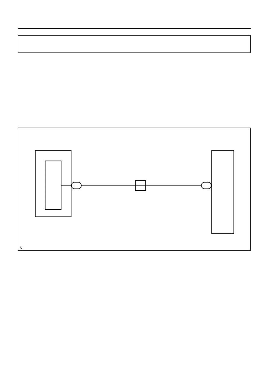
Combination Meter
SPD
G–O
25
C5
3
R29
J17
J/C
B
Radio and Navigation Assy
B
G–O
–
DIAGNOSTICS
NAVIGATION SYSTEM
DI–2291
2485
Speed signal circuit
CIRCUIT DESCRIPTION
The navigation ECU (built in the radio and navigation assy) receives a vehicle speed signal from the com-
bination meter assy and information about the GPS antenna, and then adjusts vehicle position.
HINT:
A voltage of 12 V or 5 V is output from each ECU and then input to the combination meter. The signal
is changed to a pulse signal at the transistor in the combination meter. Each ECU controls the respec-
tive system based on the pulse signal.
If a short occurs in an ECU, all systems in the speed signal circuit will not operate normally.
WIRING DIAGRAM
DIDDP–01
I28748
SPD
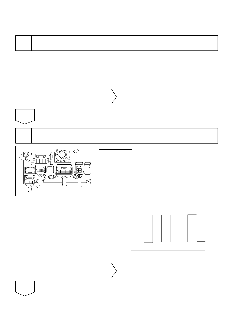
Wire Harness View:
R29
4.5 to 14 V
0
Turn the wheel
Below 2 V
DI–2292
–
DIAGNOSTICS
NAVIGATION SYSTEM
2486
INSPECTION PROCEDURE
1
Check operation of speedometer.
CHECK:
Drive the vehicle and check if the function of the speedometer in the combination meter is normal.
OK:
Actual vehicle speed and the speed indicated on the speedometer and the same.
HINT:
The vehicle speed sensor is functioning normally when the indication on the speedometer is normal.
NG
Check combination meter assy
(See page
OK
2
Inspect combination meter assy.
PREPARATION:
Disconnect the radio and navigation assy connector.
CHECK:
(a)
Move the shift lever to the neutral position.
(b)
Jack up either one of the front wheels.
(c)
Turn the ignition switch on.
(d)
Measure the voltage between terminal SPD and body
ground of the radio and navigation assy when the front
wheels are turned slowly.
OK:
Voltage is pulses as shown below.
OK
Replace radio and navigation assy.
NG
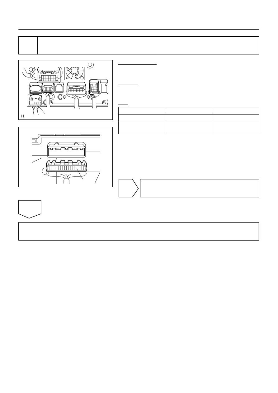
I28748
Radio and Navigation Assy:
SPD
R29
I28569
Combination Meter Assy:
C5–25
–
DIAGNOSTICS
NAVIGATION SYSTEM
DI–2293
2487
3
Check harness and connector (Combination meter assy – Radio and navigation
assy).
PREPARATION:
Disconnect the radio and navigation assy and combination me-
ter assy connectors.
CHECK:
Measure the resistance according to the value(s) in the table
below.
OK:
Tester connection
Condition
Specified condition
SPD (R29–3) – C5–25
Ignition switch OFF
Below 1
Ω
SPD (R29–3) –
Body ground
Ignition switch OFF
10 k
Ω
or higher
HINT:
If the resistance between terminal SPD and body ground is less
than 10 k
Ω
, there may be a short in a wire harness, connector,
or ECU.
NG
Repair or replace harness or connector.
OK
Replace combination meter assy.
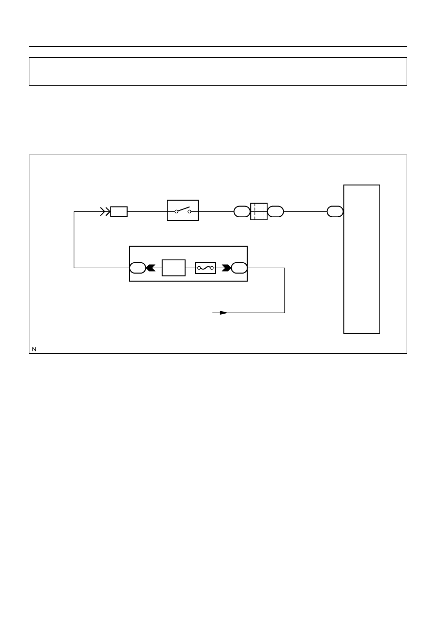
I28481
Radio and Navigation Assy
P1
Park/Neutral Position Switch
Instrument Panel J/B
REV
IG4
J/C
J51
J52
From Ignition
Switch
R29
IPO
RAD No. 2
1D
1C
RB
RL
L–R
B–Y
5
F
H
L–R
B–Y
L–R
7
1
8
6
9
1
2
DI–2294
–
DIAGNOSTICS
NAVIGATION SYSTEM
2488
Reverse signal circuit
CIRCUIT DESCRIPTION
The radio and navigation assy receives the reverse signal from the park/neutral position switch and informa-
tion about the GPS antenna, and then adjusts the vehicle position.
WIRING DIAGRAM
DIDDQ–01
Нет комментариевНе стесняйтесь поделиться с нами вашим ценным мнением.
Текст