Toyota Sequoia (2005). Manual — part 382
–
DIAGNOSTICS
SUPPLEMENTAL RESTRAINT SYSTEM
DI–1323
1517
2
Check connection of connectors.
PREPARATION:
(a)
Turn the ignition switch to the LOCK position.
(b)
Disconnect the negative (–) terminal cable from the battery, and wait for at least 90 seconds.
CHECK:
Check that the connectors are properly connected to the occupant classification ECU and the airbag sensor
assembly.
OK:
The connectors are connected securely.
NG
Connect connectors, then go to step 1.
OK
3
Prepare for inspection.
PREPARATION:
CAUTION:
Be sure to perform the following procedures before troubleshooting to avoid unexpected airbag de-
ployment.
(a)
Disconnect the connectors from the airbag sensor assembly.
(b)
Disconnect the connectors from the steering wheel pad.
(c)
Disconnect the connectors from the front passenger airbag assembly.
(d)
w/ Side and curtain shield airbag:
Disconnect the connectors from the side airbag assembly LH and RH.
(e)
w/ Side and curtain shield airbag:
Disconnect the connectors from the curtain shield airbag assembly LH and RH.
(f)
Disconnect the connectors from the front seat outer belt LH and RH.
NEXT
C84205
G27650
H24003
Occupant
Classification ECU
Airbag
Sensor
Assembly
D
A21
FSR–
FSR+
C
B
A
E
F
C84207
G27650
H43694
H24002
Occupant
Classification ECU
Airbag
Sensor
Assembly
D
FSR–
FSR+
C
B
A
FSR+
FSR–
O6
E
F
A21
Service Wire
DI–1324
–
DIAGNOSTICS
SUPPLEMENTAL RESTRAINT SYSTEM
1518
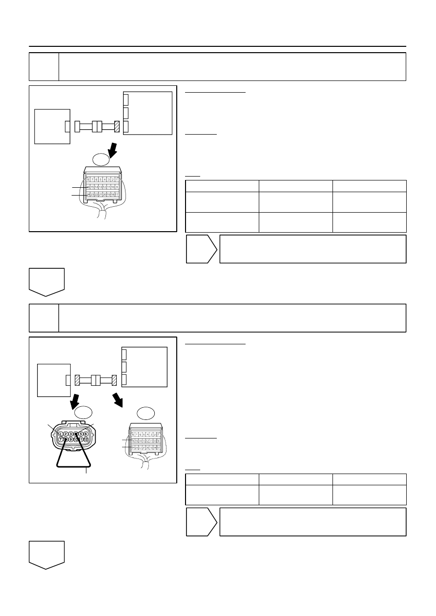
4
Check airbag sensor assembly communication circuit (short to B+).
PREPARATION:
(a)
Disconnect the connector from the occupant classifica-
tion ECU.
(b)
Connect the negative (–) terminal cable to the battery.
CHECK:
(a)
Turn the ignition switch to the ON position.
(b)
Measure the voltage according to the value(s) in the table
below.
OK:
Tester Connection
Condition
Specified Condition
A21–16 (FSR+) –
Body ground
Ignition switch ON
Below 1 V
A21–24 (FSR–) –
Body ground
Ignition switch ON
Below 1 V
NG
Go to step 13.
OK
5
Check airbag sensor assembly communication circuit (open).
PREPARATION:
(a)
Turn the ignition switch to the LOCK position.
(b)
Disconnect the negative (–) terminal cable from the bat-
tery, and wait for at least 90 seconds.
(c)
Using a service wire, connect O6–8 (FSR+) and O6–4
(FSR–) of connector ”E”.
NOTICE:
Do not forcibly insert a service wire into the terminals of the
connector when connecting.
CHECK:
Measure the resistance according to the value(s) in the table
below.
OK:
Tester Connection
Condition
Specified Condition
A21–16 (FSR+) –
A21–24 (FSR–)
Always
Below 1
Ω
NG
Go to step 14.
OK
C84205
G27650
H24003
Occupant
Classification ECU
Airbag
Sensor
Assembly
D
A21
FSR–
FSR+
C
B
A
E
F
C84205
G27650
H24003
Occupant
Classification ECU
Airbag
Sensor
Assembly
D
A21
FSR–
FSR+
C
B
A
E
F
–
DIAGNOSTICS
SUPPLEMENTAL RESTRAINT SYSTEM
DI–1325
1519
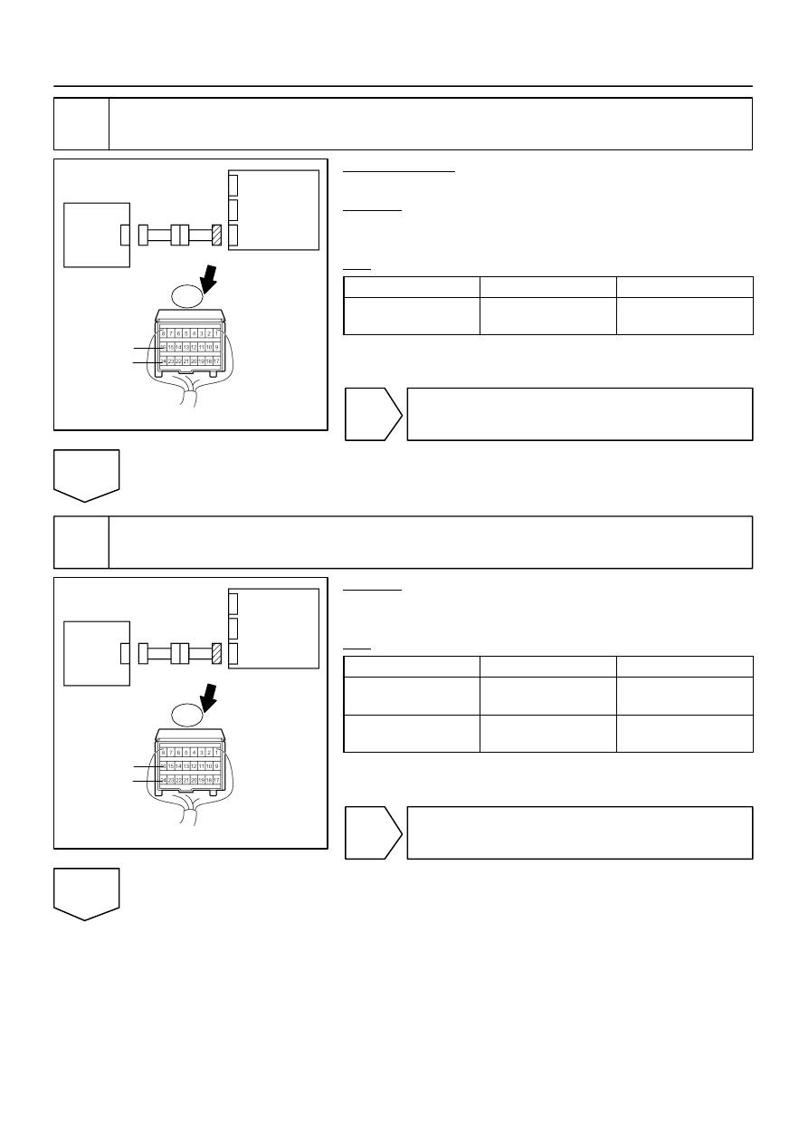
6
Check airbag sensor assembly communication circuit (short).
PREPARATION:
Disconnect the service wire from connector ”E”.
CHECK:
Measure the resistance according to the value(s) in the table
below.
OK:
Tester Connection
Condition
Specified Condition
A21–16 (FSR+) –
A21–24 (FSR–)
Always
1 M
Ω
or higher
NG
Go to step 15.
OK
7
Check airbag sensor assembly communication circuit (short to ground).
CHECK:
Measure the resistance according to the value(s) in the table
below.
OK:
Tester Connection
Condition
Specified Condition
A21–16 (FSR+) –
Body ground
Always
1 M
Ω
or higher
A21–24 (FSR–) –
Body ground
Always
1 M
Ω
or higher
NG
Go to step 16.
OK

DI–1326
–
DIAGNOSTICS
SUPPLEMENTAL RESTRAINT SYSTEM
1520
8
Check DTC.
PREPARATION:
(a)
Connect the connectors to the occupant classification ECU and the airbag sensor assembly.
(b)
Connect the negative (–) terminal cable to the battery.
CHECK:
(a)
Turn the ignition switch to the ON position.
(b)
Clear the DTCs stored in memory (see page
).
HINT:
First clear DTCs stored in the occupant classification ECU and then in the airbag sensor assembly.
(c)
Turn the ignition switch to the LOCK position.
(d)
Turn the ignition switch to the ON position.
(e)
Using the hand–held tester, check the DTCs of the occupant classification ECU (see page
OK:
DTC B1790 is not output.
HINT:
Codes other than DTC B1790 may be output at this time, but they are not related to this check.
NG
OK
From the results of the above inspection, the malfunctioning part can now be considered normal.
To make sure of this, use the simulation method to check (see page
Нет комментариевНе стесняйтесь поделиться с нами вашим ценным мнением.
Текст